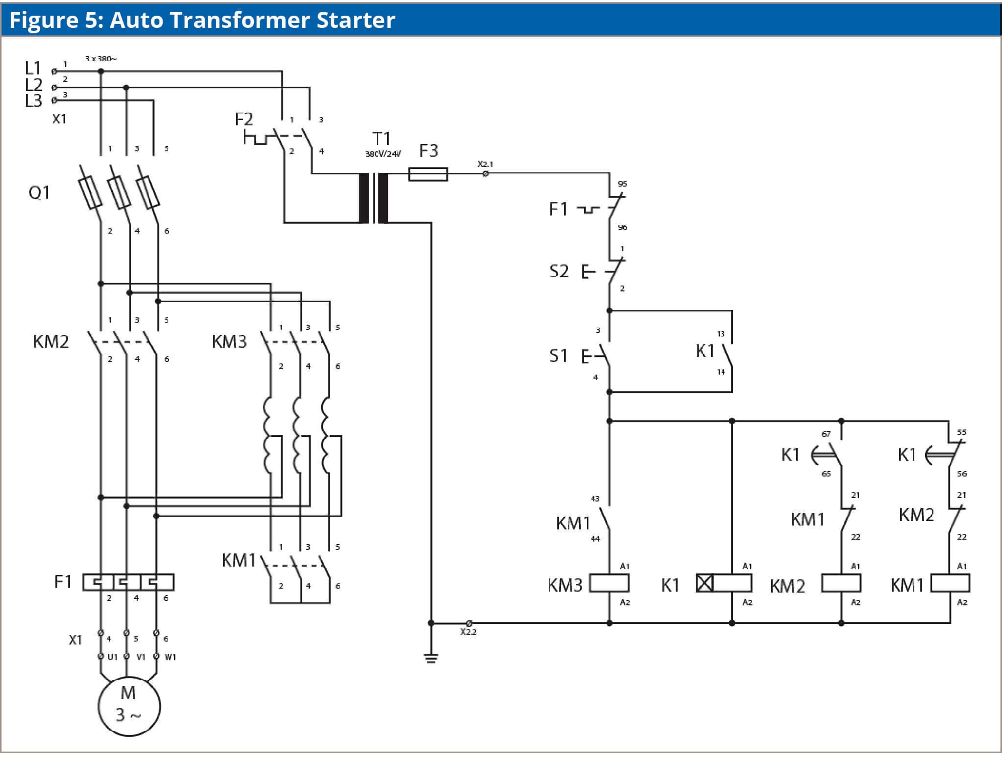
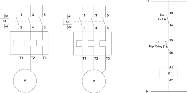
2 three phase supply 415. In the above one phase motor wiring i first connect a 2 pole circuit breaker and after that i connect the supply to motor starter and then i do cont actor coil wiring with normally close push button switch and normally open push button switch and in last i do connection between capacitor start motor and contactor.

Single Phase Two Speed Motor Wiring Diagram Escaperoomfortworth
Dol wiring diagram single phase. 13 17 with a flying lead to be connected to overload terminal 95. 3 phase motor wiring diagram fresh mem dol starter wiring diagram motor starter wiring diagram start stop reference start stop switch a pcb from another source can be used in replacing the electronics in a standard device or giving communications to a custom controller. Pete vree 331049 views. The diagram below shows the wiring for a single phase motor and the path through the contactor and overload. A dol starter or direct on line starter or across the line starter is a method of starting of a 3 phase induction motorin dol starter an induction motor is connected directly across its 3 phase supply and the dol starter applies the full line voltage to the motor terminals. The connection of the supply to the motor is normally on the underside of the motor terminal lid loldoesnt matter which way.
The direct on line motor starter dol is designed to switch a single or three phase induction motor at rated voltage. All other control and power connections have to be made by the installer. Water pump controller with float switch duration. The run winding and the start winding the start winding is normally connected to the supply and a capacitor. Dont forget that there are two windings in a single phase motor. Ladder diagram basics 3 2 wire 3 wire motor.
The above diagram is a complete method of single phase motor wiring with circuit breaker and contactor. When the motor hits a certain speed a switch inside the motor disconnects the start winding. This diagram illustrates possible wiring using a tesys d lc1d contactor and tesys lrd overload lrd and stop control is assumed to be by operation of the stop button on the overload. Despite this direct connection no harm is done to the motor. The thermal overload is supplied as a separate item. It comprises an enclosure in steel or plastic a contactor start contact link wires and stop start buttons.
1 22kw motor with a flc of 5 amps at 415volts. A2 14 18. Please see the attached diagram for guidance. 3 phase dol starter control and power wiring diagram. Properly connect a single phase motors to a three phase starter. Wiring of the direct on line dol motor starter 1 three phase supply 230volt coil see wiring diagram.
In the below dol starter wiring diagram i shown a molded case circuit breaker a magnetic contactor normally open push button normally close push button switch thermal overload relay motor trip indicator and 3 phase motor. What is dol starter. Three phase dol starter control overload. 1 the following links are pre fitted to the starter. Ryb electrical 43796 views.


