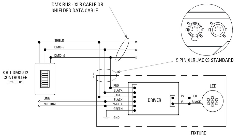
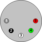
Color kinetics dmx. It is important to note that the color kinetics wiring is completely different than the esta standard.
Connector Pinouts Auschristmaslighting
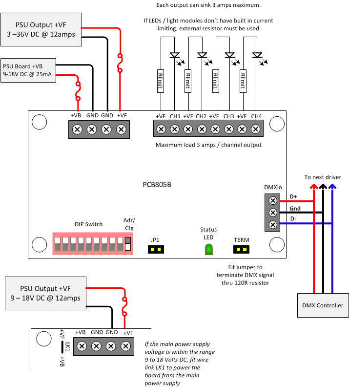
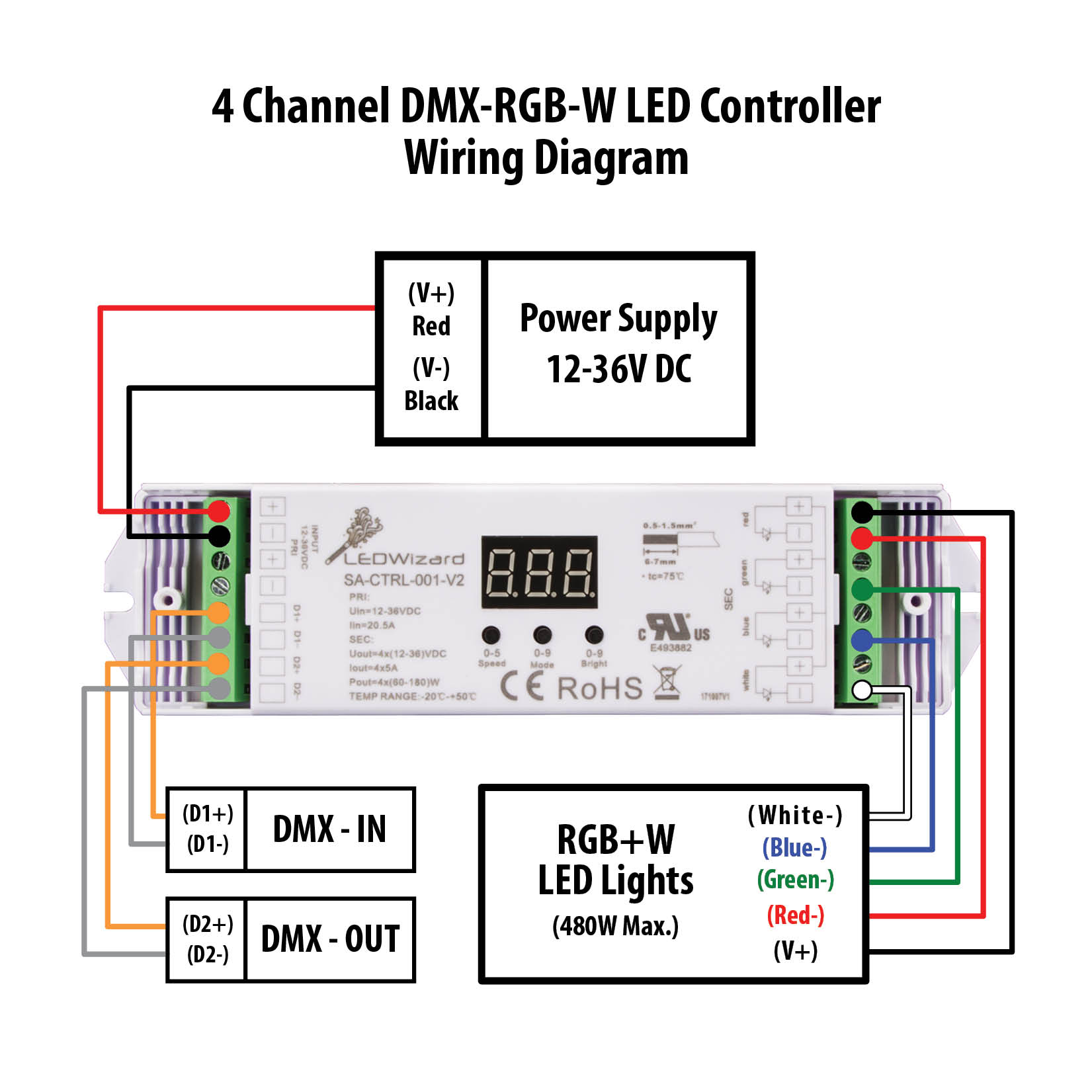
Dmx 5 pin wiring diagram. The dmx specification allows for two completely separate data channels over the one 5 pin connector but often youll find the cable manufacturers cheap out and only provide a single channel. Traditionally 3 pin connectors have been the domain of audio and 5 pin xlr connectors have been the domain of dmx control for lighting. However some older units still use the 5 pin connectors with only three pins used. Per the standard dmx uses 5 pin xlr with male being input and female being output. This was an original specification for the dmx standard but since then dmx512 a e111 2008 allows the use of eight pin modular rj 45 connectors for fixed installations where regular plugging and unplugging of equipment is not required. The last dmx device on the line must be terminated with a termination switch or resistor with a value of 100 to 120 ohms between pins 2 and 3.
The dmx data itself requires only 2 of the cable cores plus the shield so recent devices have moved to the 3 pin format. The avoidance of pins 4 and 5 helps to prevent equipment damage if the cabling is accidentally plugged into a single line public switched telephone network phone jack. There are also numerous other connection types such as 3 pin rj45 etc. Dmx cables are most commonly made with 2 core shielded data cable terminated at either end with 3 or 5 pin xlr connectors one male one female. Rj45 connectors may be used with cat5 cable for permanent wiring. Cat5 utp cable may be used inside metal conduit.
Category wire is not recommended for loose or temporary cabling. Male rj45 connectors are especially prone to breakage over repeated re connections. Wire must be belden 9829 9842 cat 5 or equivalent. Cat5 or equivalent is not preferred as a portable cable since it is not as rugged as other dmx cables. Here are the dmx 512 pinouts for each. It shows the components of the circuit as simplified shapes and the facility and signal links between the devices.
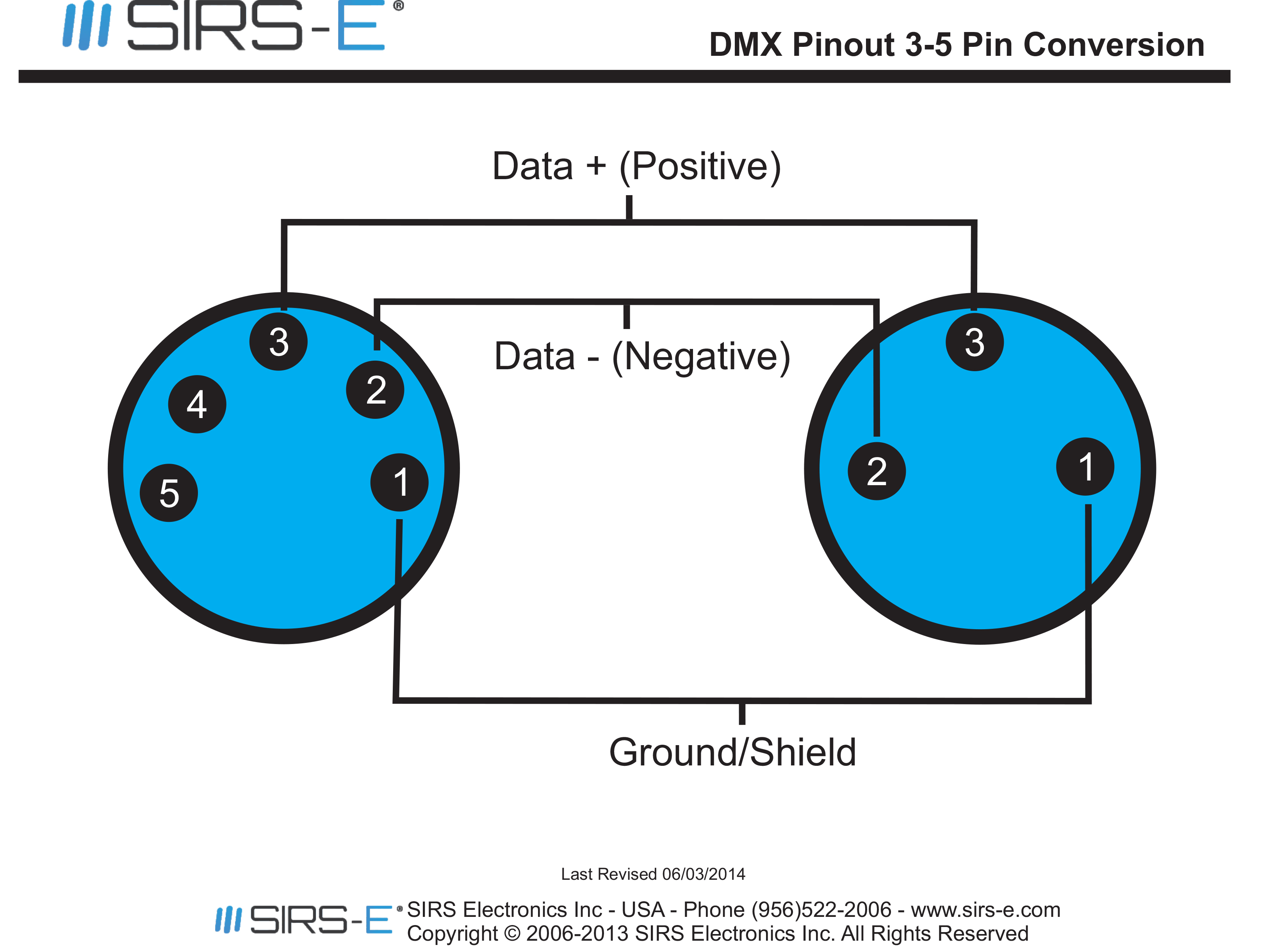
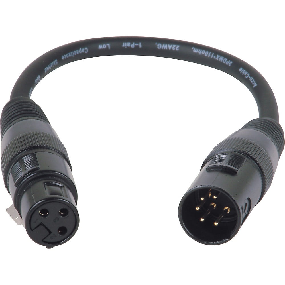
The connection of dmx equipment to non dmx equipment such as ethernet switches or telephone equipment may result in serious equipment damage andor personal injury as pins 4 and 5 may carry voltages of up to 48vdc or greater. However there are a lot of lighting fixtures which use 3 pin xlr connectors for dmx. 5 pin xlr wiring standard 5 pin xlr connectors are used primarily in lighting control applications as a dmx signal. The cabling of dmx for use with theatrical or stage setups is usually done with either 3 pin or 5 pin xlr connectors. This article explains how to made adaptors between 3 and 5 pin dmx xlr connectors. However etc supports dmx over cat5 with maximum total wire length per run of 500m1640ft.
5 pin din plug wiring diagram wiring diagram is a simplified welcome pictorial representation of an electrical circuit.
