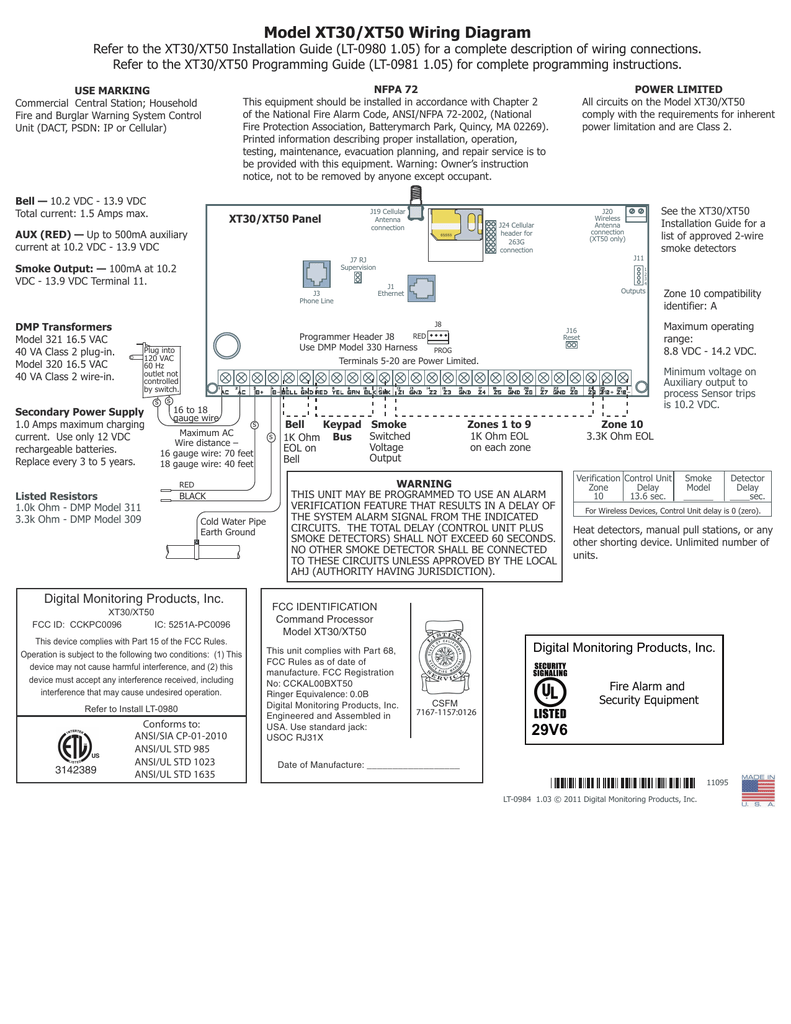
When using the xt30xt50 series control for any listing organizations approved information furnished by dmp is believed to be accurate and reliable. Model xt30xt50 wiring diagram refer to the xt30xt50 installation guide lt j16 reset red programmer header j8 use dmp model harness.
Control Panels Amp Keypads Dmp
Dmp xt30 wiring diagram. The xt30 offers 42 zones. Xt30xt50 users guide i. Dmp electronics xt30 user manual 72 pages. Security command keypads thinline aqualite icon keypads clear touch keypads. Introduction xt30xt50 users guide 3 dmp keypads your system may have one or more easy to use lcd keypads that allow you to properly operate the system. The panels connect at the premises to a standard rj31x or rj38x telephone jack.
A model 300 output harness is required. A description of each module follows. 17 enclosure specifications the xt30xt50 panel ships standard in a 340 enclosure with eol resistors battery leads users guide and. Has anybody wired an rrs mod to an xt30 with 2wta b smokes dmp also has a diagram in the xt30 manual but they have a 2w mod2. View and download dmp electronics xt30 installation manual online. Use the dmp 893a dual phone line module when connecting the panel to two separate phone lines in fire or burglary.
Xt30 and xt50 series panels and accessories to locate specific listing cards scroll to the appropriate agency category and select the link located on the right side of this page. Xt30xt50 wiring diagram power limited operation testing maintenance evacuation planning and repair suitable for dact central station. Each xt panel can manage up to six areas and supports up to eight keypad addresses. The xt50 offers a maximum of 58 zones. You can program the panel for reporting to dmp scs vr or scs 1r receivers using digital dialer cellular network or contact id communication. 10 onboard and 32 via the eight keypad addresses.
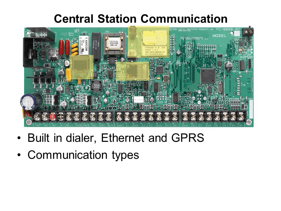
All circuits on the model xt30xt50 comply service is to be provided with this equipment. The open collector outputs provide the ground connection for a positive voltage source. Xt30xt50 installation guide digital monitoring products 3 t t system components 31 wiring diagram the system wiring diagram in figure 1 shows some of the accessory devices for use in various applications. 10 onboard and up to 32 wired or 48 wireless. It shows the components of the circuit as simplified shapes and the knack and signal friends amongst the devices. The xt30xt50 panels provide four open collector outputs rated for 50ma each.
Dmp xt30 wiring diagram wiring diagram is a simplified adequate pictorial representation of an electrical circuit.


