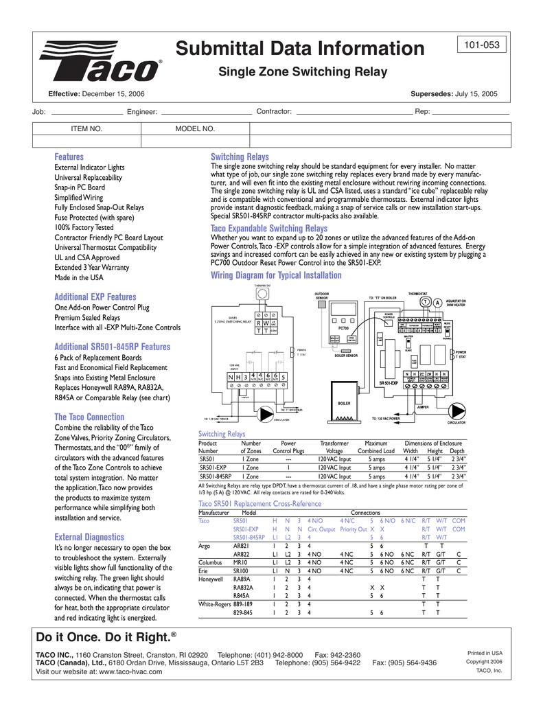
Our wiring diagrams section details a selection of key wiring diagrams focused around typical sundial s and y plans. To get from 120 v to 24 v we use a transformer.

72 Boler Restoration Electrical Work
Boler wiring diagram. This is a general guide always test before connecting your wiring. Please note that these drawings reflect the standard configuration. In a fiberglass trailer forget all you know about 12 volt automotive wiring think residential wiring. It reveals the parts of the circuit as streamlined shapes and also the power and signal links in between the tools. Faq wiring diagram combination boiler st9120 t6 and t4 additional wiring diagrams 04 20 v4043 zone valve s plan operation. Wiring diagrams for oil burning and water boilers are noted.
If you have ever followed a boler with the original tail lights you know where i am coming from. A wiring diagram is a simplified traditional pictorial representation of an electric circuit. A wiring diagram is a streamlined standard pictorial depiction of an electric circuit. Variety of central boiler thermostat wiring diagram. The options selected for a particular unit may affect the actual drawing required. Boler still matching any original wiring diagrams is somewhere between zero and none.
However most gas boilers you will be working on have 24 v controls. Wellborn assortment of steam boiler wiring diagram. This is fine if the boiler is 120 v. Wiring diagrams most of the wiring diagrams are for natural gas powered steam boilers. As the wiring is old and very susceptible to having been damaged over the years i always tear out whatever is left and start from scratch usually with a progressive dynamics pd 4045 power center. This wiring diagram shows 120 v coming from l1 of a circuit breaker through a switch powering a boiler control and returning through l2 back to the neutral bar of the circuit breaker box.
A copy of the actual wiring diagram used ships with the unit. August 17 2018 by larry a. Zone valve wiring diagrams boiler wiring diagrams wiring f or 4 wire zone valve low voltage 120 volts 120v 24v boiler connections t 1 t 2 3 zone valve hot neutral. Ct 6 10 15 and 25 boiler wiring diagram. It shows the elements of the circuit as streamlined shapes as well as the power as well as signal connections in between the gadgets. Not to mention the chances of your almost 40 yo.


