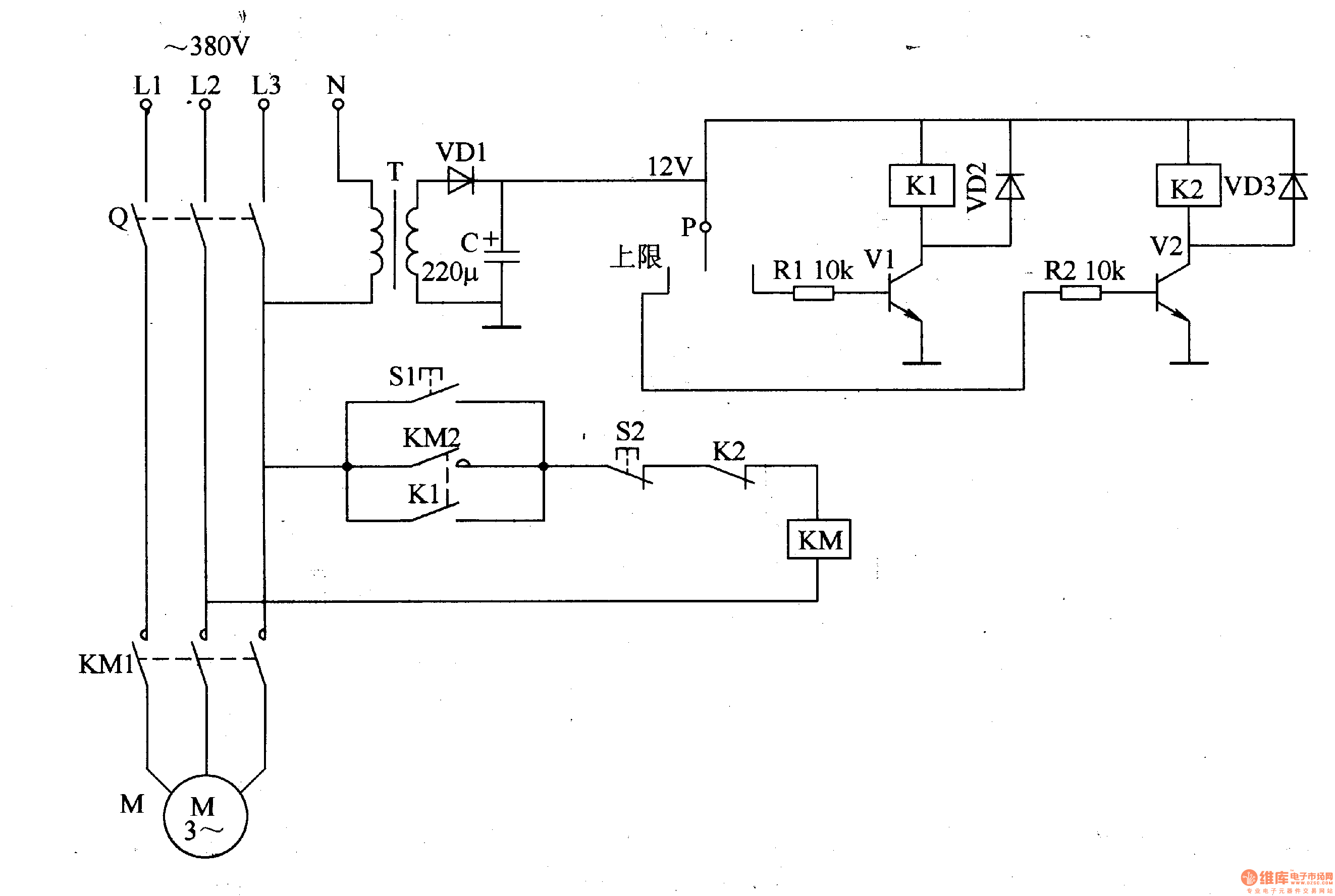
It shows the components of the circuit as simplified shapes and the gift and signal friends in the middle of the devices. Gage reading is unaffected by.

Dr 7092 Water Flow Pressure Switch Wiring Diagram Schematic
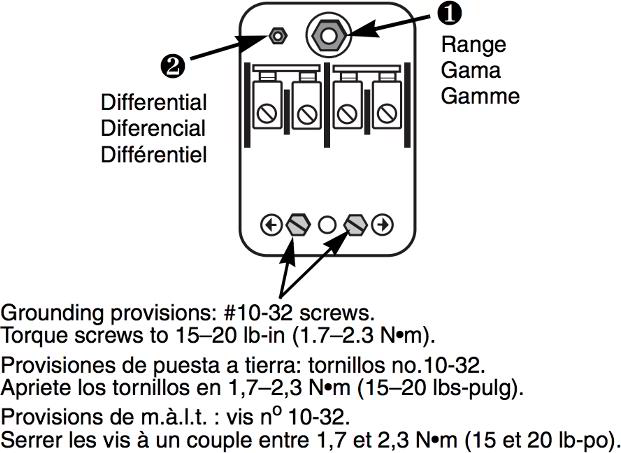
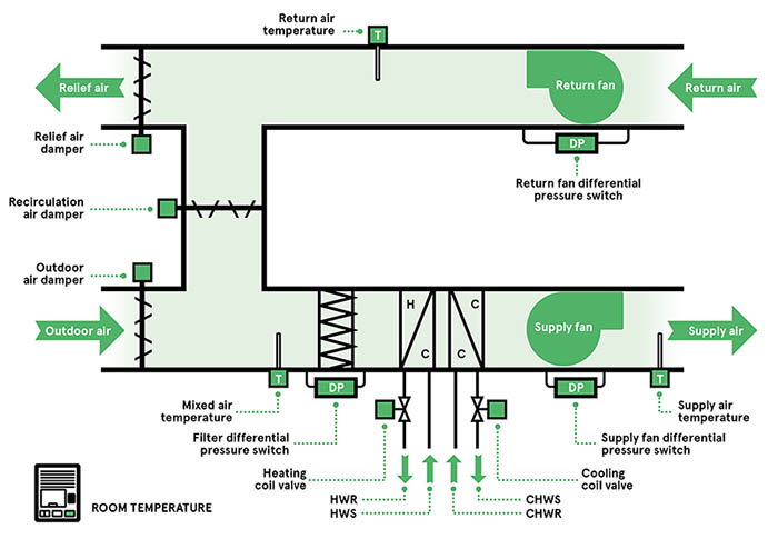
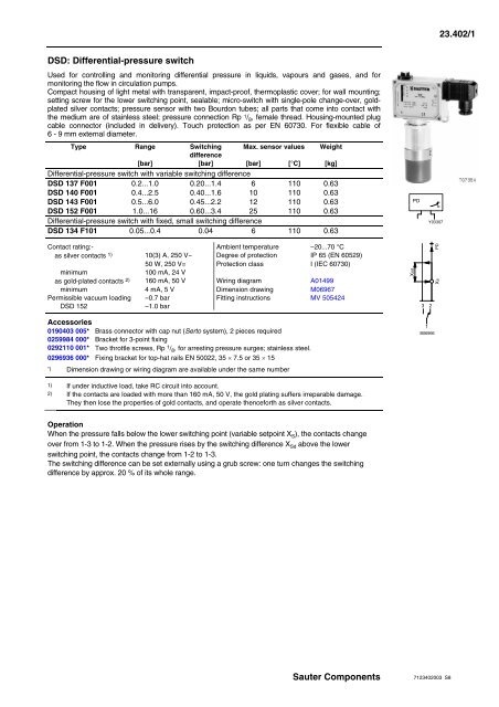
Differential pressure switch wiring diagram. The light informs the driver that theres a problem with the base braking system. It is designed to measure and control positive negative or differential pressure of air or other non combustible non corrosive gases. The series a3000 photohelic switchgage is a versatile 2 in 1 instrument combining a time proven magnehelic differential pressure gage with lowhigh pressure switches. Oil pressure switch wiring diagram wiring diagram is a simplified all right pictorial representation of an electrical circuit. In this video we show you the best way to a pressure switch for 115v and 230v pumps. A wiring diagram usually gives opinion roughly the relative point of view and understanding of devices and terminals on the devices to assist in building or servicing the device.
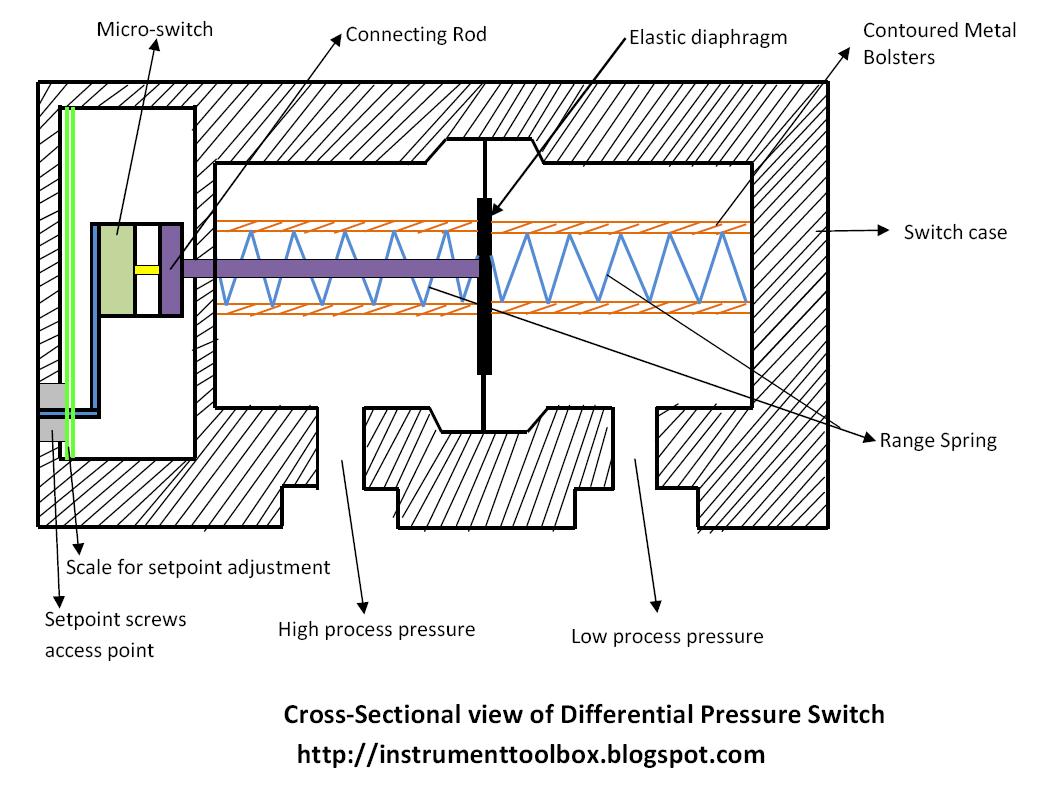
Watch as danfoss own will guides you through two different ways to wire an mp differential pressure switch which is used to protect refrigeration compressors against low lubricating oil pressure. When the pressures from two different sources in a process are connected across the sensing diaphragm metallic or elastomeric as the case may be the pressure difference creates a force which then overcomes that of a pre tensioned spring and in the. The pressure differential switch illuminates the red brake warning light when theres a difference in pressure between the two hydraulic circuits of a dual master cylinder. This method will work for any pump that runs directly off of a pressure switch including jet pumps well. A differential pressure switch is designed to sense a difference in pressure between two pressure sources in the plant for control purposes.


