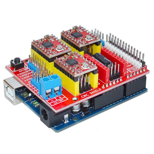
Mach3 tested settings for spindle relay and pwm control. It can control on five axis at the same time please follow the instructions or import the cd configuration file mach3millxml.
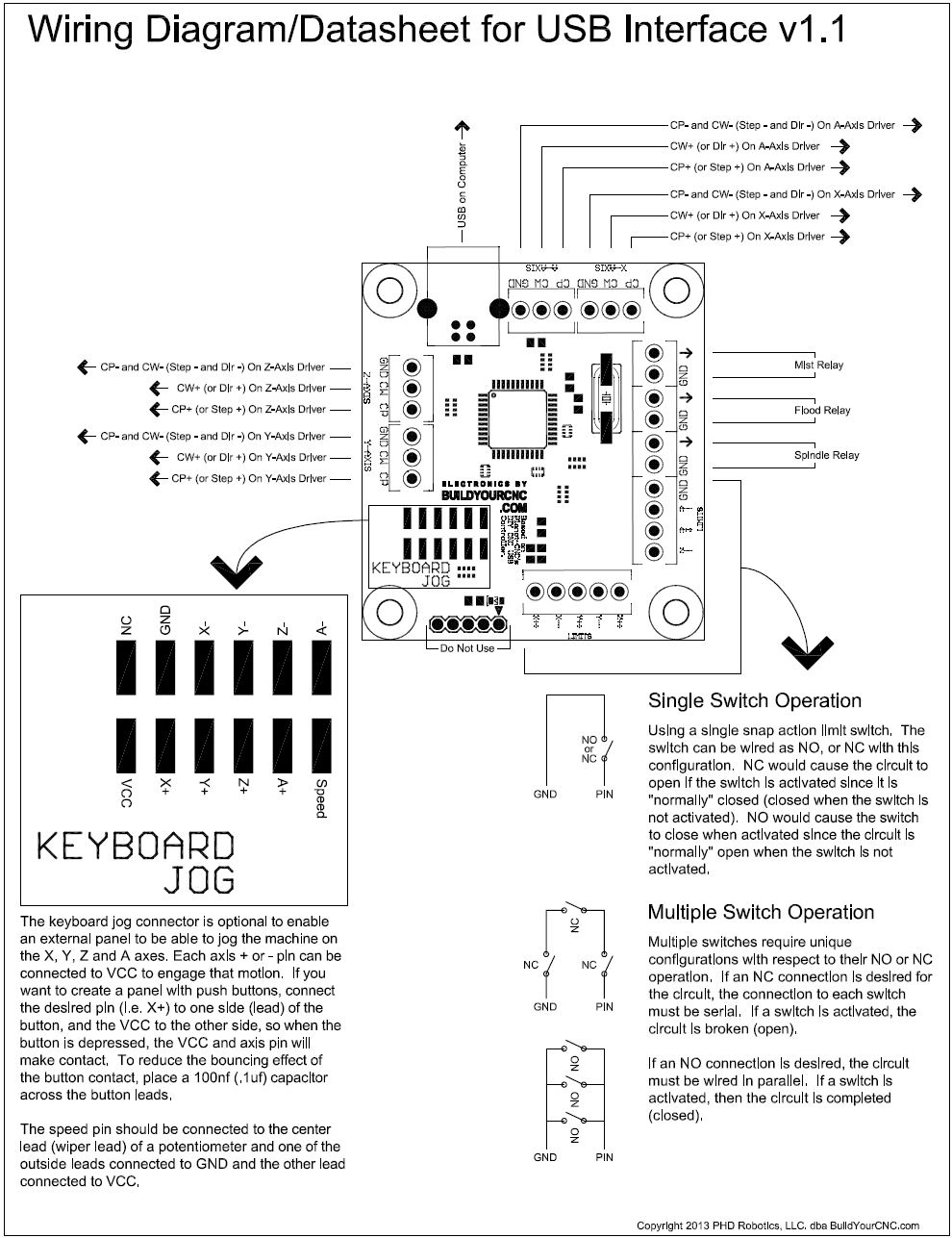
Ecada Switches For Cnc Wiring Diagram Wiring Library
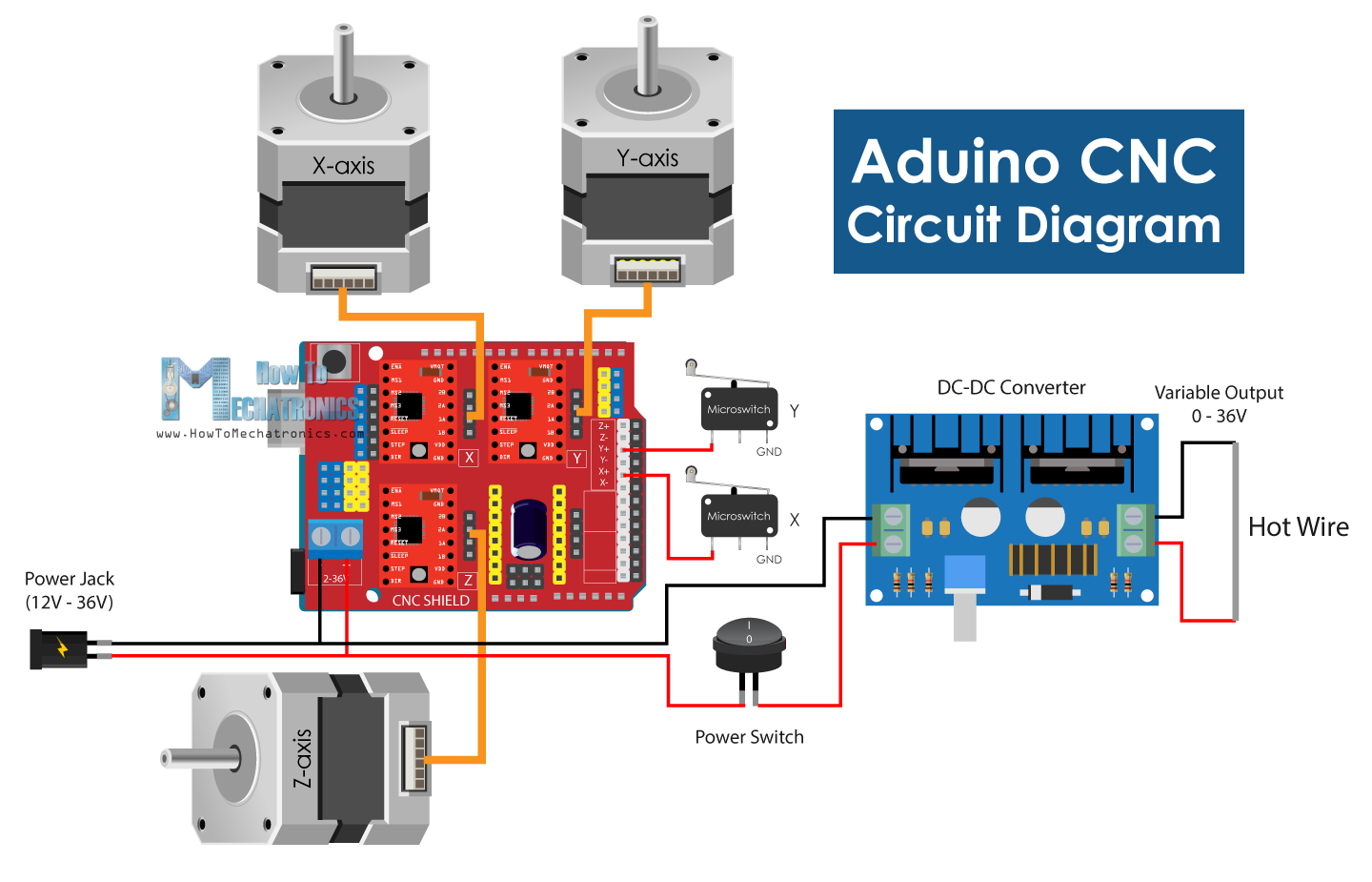
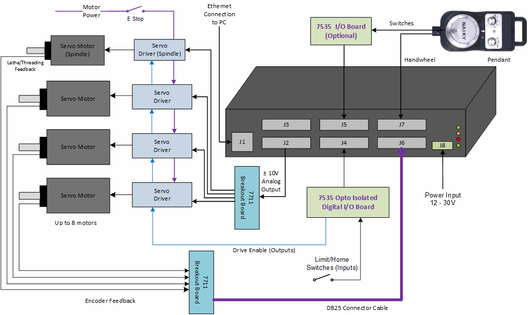
Cnc interface board st v3 wiring diagram. 5 axis breakout board. Board pdf press the link below. There are several different types of cnc breakout boards and related devices used to deliver this io inputoutput capability including parall el cnc breakout board s usb breakout boards. 3 axis tb6560 cnc driver board user manual st 6560v3 3 3. The wiring of the parallel breakout board from the output terminals to the driver digital pulse step pulse and direction lines are explained. Wiring diagram for power supplies v posv c v com gnd l n l n l n switch mode psus 48 volt with our low inductance nema 23 stepper motors page 3.
Go to the new parallel breakout board to get more information and the wiring diagram. Incorrect wiring of the stepper motor to the drive board can lead to immediate damage of drive board do not connect or disconnect motors while power is on. Cck to st v3 breakout board. 4 wire 6 wire and 8 wire stepper motors can be used. Hardware installation 31 selecting and connecting stepper motors warning. 5 axis breakout board driver wiring example duration.
The cnc breakout board is used to interface between your pc and the various motor controls relays and other devices you want to control on a cnc machine. Xml st v3 file set up for mach3 press here. Mach3 5 axis cnc breakout board v 3. It is new breakout board model st v3 diagram wiring. Noteall the stetings below is for common anode connection between this interface board and the stepping motor drivlers mach3 soft setting afirst check mach3 driver is install well notemach3 drivercant has or bsoft setting 1unit select. X axis wiring diagram yel blk wht brn red blu org grn a a b b vcc gnd p1 p3 p2 vcc gnd vcc gnd vcc gnd v c c g n d psu 5v regulated 500ma.
Whats in the package 1 x 5 axis cnc breakout board 1 x db25 parallel cable 1 x usb cable 1 x cd note. This board has no pwm and 0 10v output. Cnc machine control. The new parallel breakout board appears a bit different but the process of wiring and testing is the same. Step 3 you need to wire the driver with st v3 breakout board. Digital driver cck to power supply.
Operation of your cnc or automated machinery.


