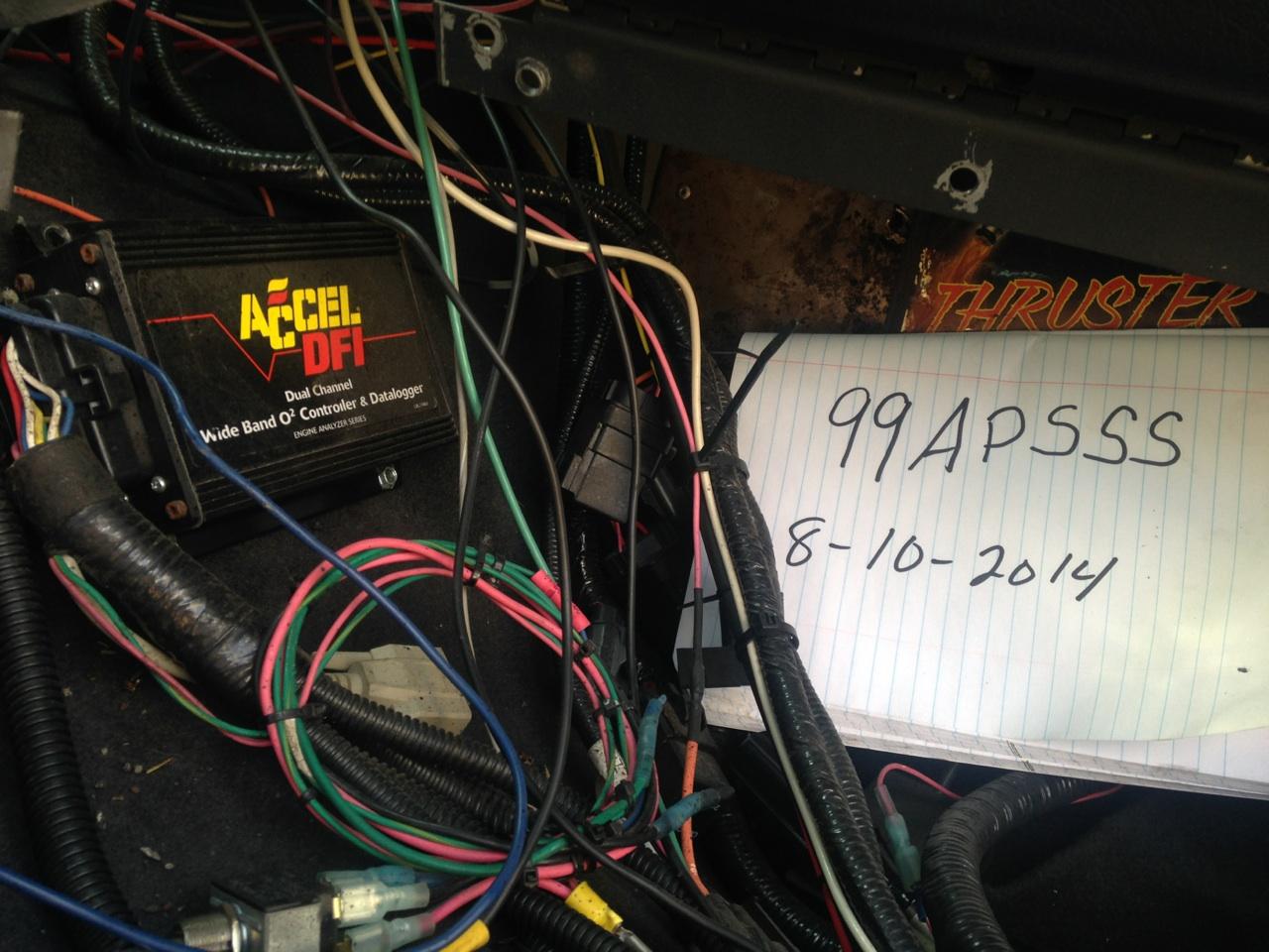
Accel dfi wiring diagram disclaimer. Pic is of the swap 95 teksid block and stock refreshed internals 99 continental c heads and cam.
Where Is The Accel Dfi Tach Signal Connection Wire Page 3
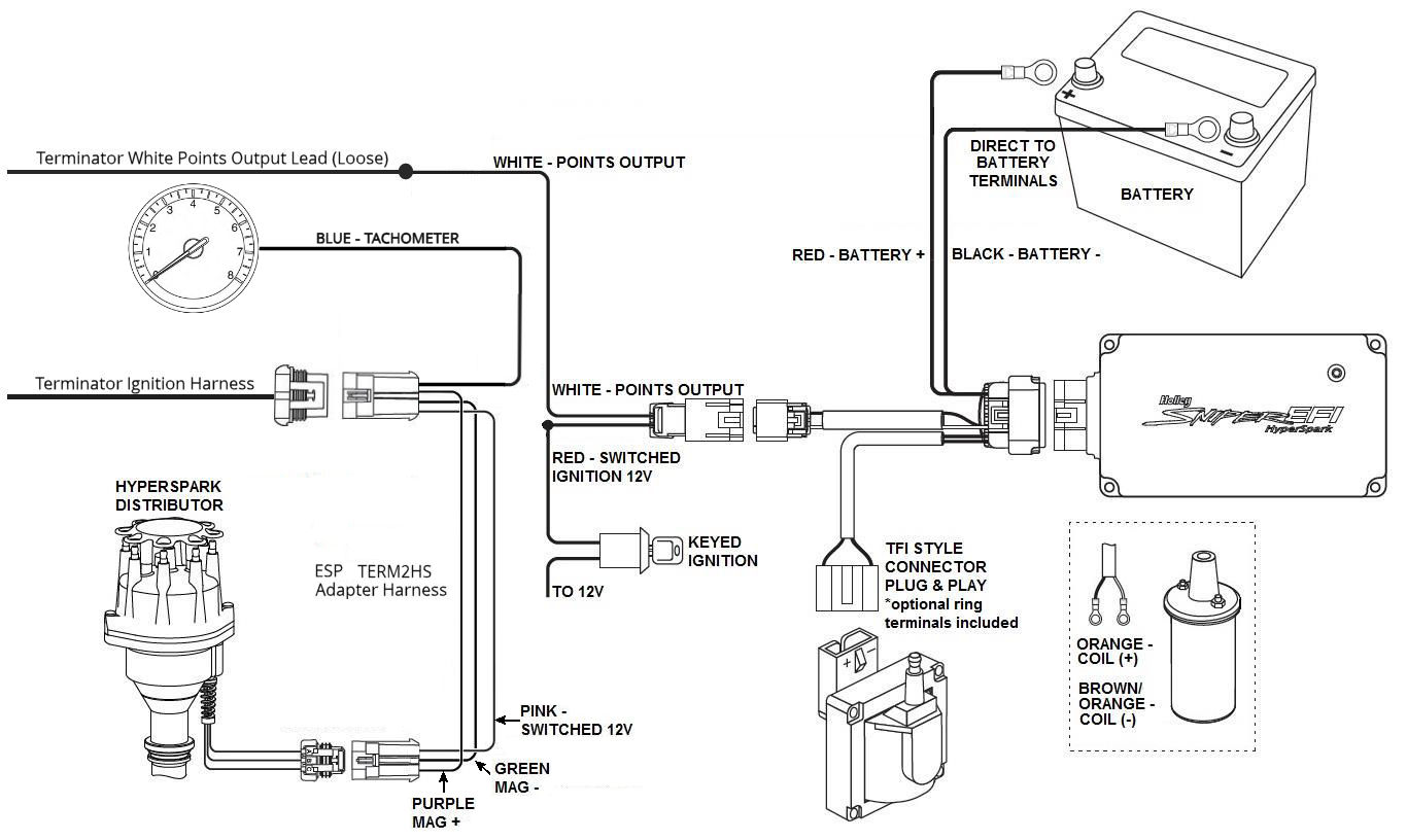
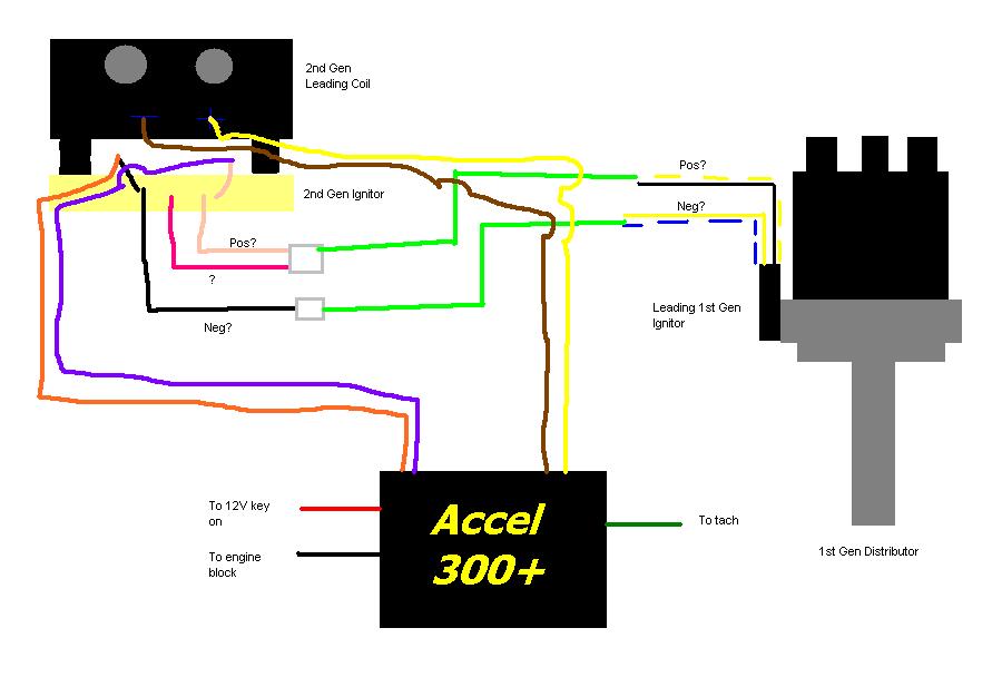
Accel dfi gen 7 wiring diagram. The part number for this kit is 77063s. Acceldfi acceldfi an overview schematic of the main wiring harness mwh is shown in figure b page 23. Pontiac 350 engine. Accel usb key. Jump to latest follow 1 4 of 4 posts. Wire such as accel 300 or accel rfi suppression wires.
¾ if you are connecting the control module to an accel dfi generation 7 system the 4 pin square male connector in the main harness will have a corresponding female connector in the generation 7 system harness labeled as hego. The harness can be routed and connected as follows. Each module also includes several advanced functions that set it apart from the competition. Acceldfi generation 7 programmable engine management systems most capable in additioneach and every dfi generation 7 engine control module is capable of controlling a wide variety of both standard and optional accessory items. Then route the longer of the two legs through the drivers side. Thankfully most everything is labeled but i am in need of the ignition wiring diagram hopefully running a stock ford edis 8.
Accel gen vii univers 4cyl spkfuel. An overview diagram of the main wiring harness is shown at the end of this section. Accel usb key sportsman. Please reference this when making. Online access to help schematics and wiring diagrams an additional 8 status indicators are available through the gen 7 logging feature a dfi exclusiveaccel dfi gen 7 wiring diagram thank you for visiting our site this is images about accel dfi gen 7 wiring diagram posted by maria rodriquez in diagram category on nov 13 you can also. These connectors should be joined as per diagram a.
Accel gen 7 wiring diagram. 46 4v accelholley dfi gen 7 wiring help. We have encountered problems including not. Acceldfi engine management systems dfi generation 70 installation and operation manual. Any help would be appreciated. We never admit that the image is our image the copyright is in the image owner we only help our users to find the information they are looking for quickly.
Begin by connecting the 32 pin and 24 pin ecm connectors to the acceldfi ecm making sure that the tabs snap into place. If you want the image to be deleted please contact us we will delete it from our website. 7 acceldfi oxygen 3 pin female black connector injector 5 pin round white connector.


