Wiring a happ joystick to a zero delay encoder. Anyone with an ignition wiring diagram am replacing column ignition switch and possibly the whole start circuit all the way from fuse box to the solenoid if needed.

A Super Easy Arcade Machine From 1 Sheet Of Plywood 15
Zero delay wiring diagram. Single coils humbuckers humsingsing humsinghum and much more. Guitar wiring diagrams for tons of different setups. Zero delay joystick adapter from the backside. A line diagram gives the necessary informa tion for easily following the operation of the various. So youve just received your zero delay arcade usb encoder and its time to wire it up. Thanks to a kind reader for straightening this all out for us.
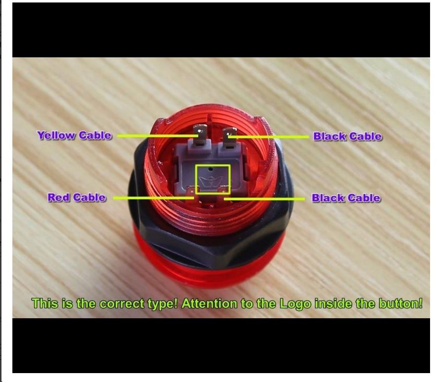
Special notes about the wiring. September 27 2016 081723 am yep the encoder if ordered for a happ joystick will come with 4 2 wire wires rather than the sanwa type that comes with a single 5 pin wire. Make this button box 32 function w encoders duration. Plus info on switches pots coil splitting and more. Placa usb zero delay revisamos todas sus funciones video definitivo duration. Time delay module 5023310 2 1 4 3 5 violet black 1 rc 5 4 3 2 time delay module schematic 32 5 4 engine magneto white voltage regulator fuel solenoid violet 25hp kawi engine jumper harness 5401329 1 23 4 5 blue yellow yellow gray orangewhite yellow orangewhite 12 5 6 34 7 8 43 8 7 21 6 5 20a 20a 20a 20a fuse block harness 5401328 red red.
Sx2dv200 and sx2dv203 wiring diagram approximate dimensions 11 14 12 0v volts ac 110 127 220 240 11 12 14 l1 l2 stop start m1 ol m 11 14 12 0v volts ac 110 127 220 240 11 12 14 l1 l2 stop start m1 ol m. Reply 1 on. Why is there a quantity limit on buttons or other products from your website. Arcade usb encoder wiring guide. We used to think that the chinese inverted the wires on it as we thought that ground was what is going all around the board. Jungla arcade 11235 views.
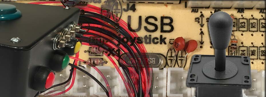
Start by getting the usb encoder pcb board and take note of the connections. On the ignition switch and through the neutral safety switch is a purple 10 and at the start terminal on the solenoid is a red. Shipping carrier server outages and current status. What is the difference between the japanese american style zero delay controls set. A wiring diagram gives the necessary information for actually wiring up a group of control devices or for physically tracing wires when trouble shooting is necessary. The wiring diagrams heavy lines.
Picture compliments of one of our readers chris. We are going to wire up the joystick first so grab that and the ribbon cable. Adjust the start up time delay potentiometer to the desired time delay.


