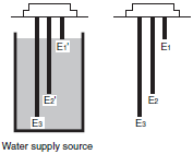
The length when using completely insulated 600 v 3 core 075 mm 2 cabtire cables. Floatless level switch 61f g ap compact type omron 61f g supply voltage ac 110220v general purpose application g control of ordinary purified water or sewage water length cable max.

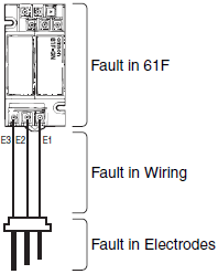
Troubleshooting
Wiring diagram wlc omron 61f g1 ap. Wiring diagram wlc omron 61f g ap images 246 part of wiring diagram free save your favourite image or wallpapers. Cara membaca diagram wiring kelistrikan yang benar duration. Wiring diagram panel amf ats with contactor duration. 1 000m range name 61f g supply voltage ac 110220 v power consumption 35 va electrical durability with load 500 000 operations mechanical durability at no load 5 000 000 operations. Edo galung 22475 views. View and download omron 61f g manual online.
Control panel pompa submersible menggunakan omron 61f g ap. Supply voltage 100 110 120 200 220 or 240 vac. Cara pemasangan wlc water level control omron 61f g1 ap. 61f g switch pdf manual download. Orders will not be accepted after march 31 2018. It is recommended to select save from the right click due to large size of manual pdf data.
The designations ta tb and tc sometimes. Eral 61f s wiring. 61f g at n 4 note. Cara pemasangan wlc water level control omron 61f g1 ap duration. Application g1 61f g1 base x 1 61f 11 at units x 2 61f g1 61f g1l 2km 61f g1l 4km 61f g1h. Please note some product models not sold in thailand may be included in the following manuals for our global customers.
Refer to the following table for the discontinued power supply voltages. 61f gp n at 3 internal circuit diagrams note. When applying a self holding circuit short between terminals 5 and 6 and use terminal 7 as e2. If you order the 61f g one 61f 11 relay unit is included in the set. Usable cable lengths will become shorter as the cable diameter or number of cores. The at in the model name represents g g1 g2 g3 g4 or i.
The schematic diagrams shown belo w typify the internal connections of the various 61f models. 61f gp n nt nl nd 61f gp nr61f gp nh 3 94 11 10 1 u 24 v 8 v control circuit s 0 s 1 e 3 5 e 1 ta 1 tc 1 tb 1 7 6 8 u ta 2 tc 2 tb 2 3 4 11 10 1. 61f g1 61f g2 61f g3 61f g4 61f i 61f 11.


