The live feed ensures the run on timer operates. How to wire bathroom fan extractor fan with timer and fan isolator duration.

How To Wire Bathroom Fan Extractor Fan With Timer And Fan Isolator
Wickes extractor fan wiring diagram. It can also be adapted for separate switching if required. Never work on a live circuit you must ensure that the circuit that you are working on is isolated and cannot be switched back on accidentally. Discussion in electricians talk started by glob at l jun 13 2019. The time lag switch will allow the fan to be manually started but then run for a pre set time. The fan im connecting is manrose gold with over run timer. Hi this video is about wiring a bathroom extractor fan wiring fan to the three pole fan switch isolator and pull cord switch.
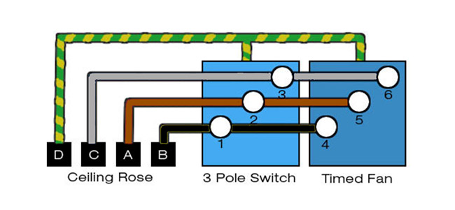
The supply for this can be taken from most existing circuits providing the switched fused unit sfu is present at the start of the installation and appropriately fused to protect the sub circuit cabling and accessories. We supply trade quality diy and home improvement products at great low prices. From the switches 3 wire cable runs to the ceiling outlet box. This article will show how to install and wire the extractor fan. Wiring a bathroom extractor fan with an isolator switch. Spend time carefully wiring up the extractor fan and make sure that you dont cut any corners.
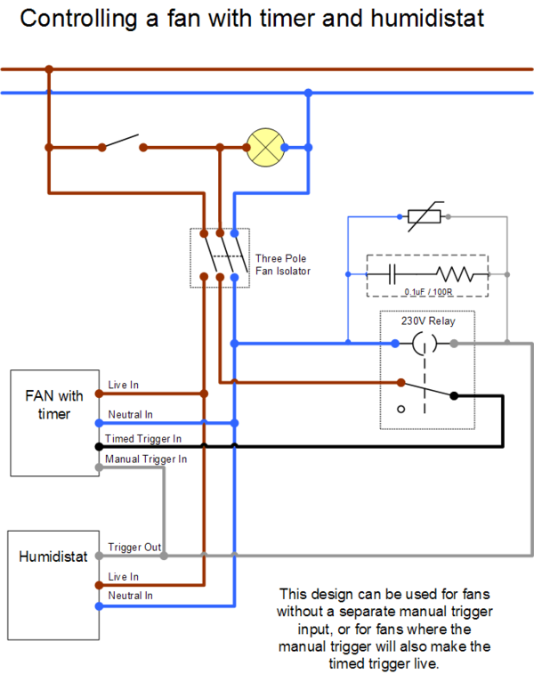
Step 1 safety. As long as you have a live switched live and neutral going to your isolator first the rest is simple to feed to the fan all as above diagram. Buy great products from our extractor fans category online at wickescouk. Lighting circuits part 3 fans motion sensor lights. A shower extractor fan is essential in a room containing a shower in order to prevent condensation. This wiring diagram illustrates the connections for a ceiling fan and light with two switches a speed controller for the fan and a dimmer for the lights.
Installing the switched fan. Options include a manual pull switch and a vacuum time lag switch. Diagram showing wiring method for an independently switched extractor fan. 3ø wiring diagrams 1ø wiring diagrams diagram er9 m 3 1 5 9 3 7 11 low speed high speed u1 v1 w1 w2 u2 v2 tk tk thermal overloads two speed stardelta motor switch m 3 0 10v 20v 415v ac 4 20ma outp uts diagram ic2 m 1 240v ac 0 10v outp ut diagram ic3 m 1 0 10v 4 20ma 240v ac outp uts these diagrams are current at the time of publication. This wiring plan will simply run the fan when the room light is on. The source is at the switches and the input of each is spliced to the black source wire with a wire nut.
Wiring up an extractor fan is a very easy process and if done safely you will be able to avoid any potential hazards and accidents which can sometimes occur.


