You need to select at least 1 product to add in your comparison list. Select at least one product to add to your shopping list.

Wrg 7511 Wiring Diagram For Motor Starter 3 Phase
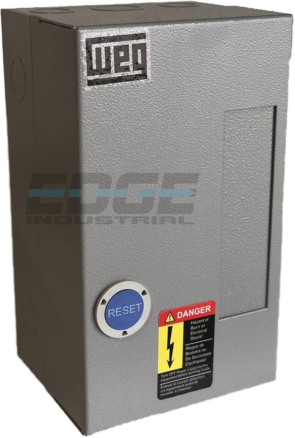
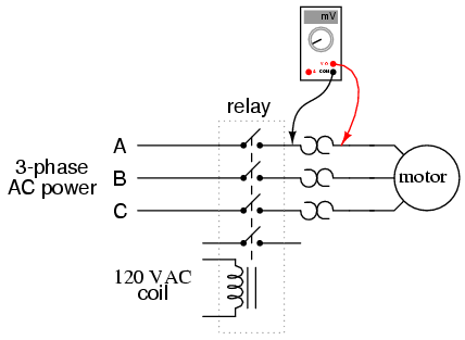
Weg motor starter wiring diagram. It shows the components of the circuit as simplified shapes and the capability and signal connections along with the devices. You need to select at least 1 product to add in your comparison list. Single phase motor starter wiring diagram weg motor capacitor wiring diagrams schematics and baldor diagram in cutler hammer starter wiring diagram. Select at least one list to add to your products. Select at least one product to add to your shopping list. Always use wiring diagram supplied on motor nameplate.
Select at least one list to add to your products. In north america an induction motor will typically operate at 230v or 460v 3 phase 60 hz and has a control voltage of 115 vac or 24 vdc. View the pesw series line here. Inst maint wiringqxd 5032008 1002 am page 6. Weg electric motor wiring diagram wiring diagram is a simplified within acceptable limits pictorial representation of an electrical circuit. Typical wiring diagrams always use wiring diagram supplied on motor nameplate connection diagrams co leads part winding weg three phase motors volts 12 lead part winding 12 10 11 12 3 l1 l2 12 10 11 64 5 78 9 12 l1 l2 12 10 11 64 5 l1 l2 starting type volts across line starting type volts soft.
Refer to the motor manufacturers data on the motor for wiring diagrams on standard frame ex e ex d etc. These diagrams are current at the time of publication check the wiring diagram supplied with the motor. A motor starter is a combination of devices used to start run and stop an ac induction motor based on commands from an operator or a controller.


