1 to 6 cph 0230stage 2 compressor cycle rate. Page 9 visionpro iaq total home comfort system locate and mount c7089u1006 outdoor important erratic temperature readings from a sensor can occur temperature sensor optional as a result of any of the wiring practices described below.

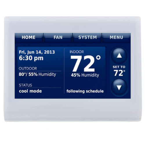
Th8321u1097 Honeywell Th8321u1097 Visionpro Programmable
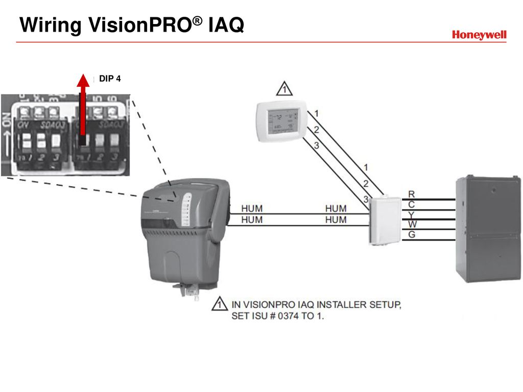
Visionpro iaq wiring diagram. Up hum hum power monitor and system fan enforcement done via thermostat. Zone panel installation guide for wiring diagrams. Position the wallplate over the holes pulling wires through the wiring opening. It shows the components of the circuit as simplified shapes and the capability and signal links with the devices. Insert the mounting screws into the holes and tighten. Visionpro iaq total home comfort system 5 68 02871 4.
Set datetime date month year press done to save changes don e tue 15 2006 6 time press done to exit don. Up software setting hunidifaettanacbon0 while fane heat is on hurridil hurrid hum. Visionpro iaq wiring diagram wiring diagram is a simplified satisfactory pictorial representation of an electrical circuit. Visionpro iaq 3 69 1816efs09 0220stage 1 compressor 1cycle rate e auto discover other options. Wiring diagram for visionpro iaq items in shaded area are included with hm506vpiaq hm509vpiaq hm512vpiaq internal control board. Avoid these practices to assure correct opera mount the sensor where see fig.
Yth9421c visionpro iaq digital programmable thermostat installation guide pdf 116 mb yth9421c visionpro iaq digital programmable thermostat operation manual pdf 241 mb visionpro iaq brochure pdf 175 mb honeywell visionpro iaq product data pdf 266 mb truesteam with visionpro iaq wiring diagram pdf 260 kb.


