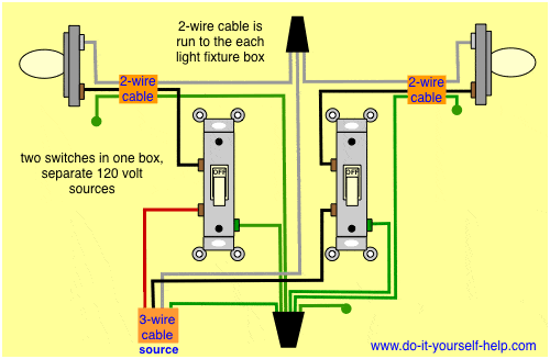
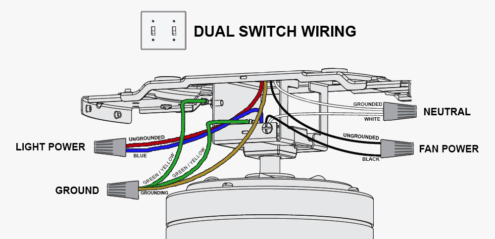
The essence of the wiring configuration is for one hot feed wire entering the switch box to be split so that it feeds both switches which in turn feed hot wires in cables that lead out to two separate light fixtures. Each component should be placed and connected with different parts in particular way.

6b007 Ceiling Fan Light Switch Wiring Diagram The Below
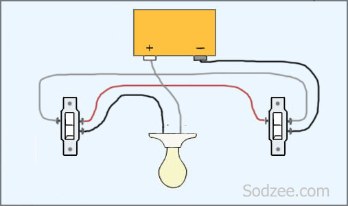
Two switch wiring diagram. Alternative method of two way switch wiring. Pin1 of both the switches are connected with the phase or live wire and pin2 of both the switches are connected with the one end of the lamp. Wiring two light switches. The hot and neutral terminals on each fixture are spliced with a pigtail to the circuit wires which then continue on to the next light. As you can see in the schematic diagram of 2 way switch circuit below the common of both the switches are short circuited. If not the structure wont function as it ought to be.
The two wire control two way switch mostly will find in some of the industrial settings and old homes. The other end of the lamp is connected with neutral line of ac power supply. Dont let this discourage you simply attach the hot wire on the new fixture exactly how you found it on the old wire. Lets assume the load you are controlling is a light. An electrical wiring diagram can be as simple as a diagram showing how to install a new switch in your hallway or as complex as the complete electrical blueprint. Two way switches and three way switches operate the same way and have the same connection points they just have different names in the uk which are common l1 and l2.
The source is at sw1 and 2 wire cable runs from there to the fixtures. Uk two way switch wiring diagram. Wiring diagrams for light switches electrical wiring diagrams home electrical wiring diagrams are an important tool for completing your electrical projects. However the actual look of the wiring in the box can vary depending on where the switches are located along the circuit run. A 2 way switch wiring diagram with power feed from the switch light. This diagram illustrates wiring for one switch to control 2 or more lights.
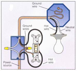
You will see that there is a hot wire that is then spliced through a switch and that then goes to the hot terminal of the light. A hot wire red or black comes out of the wall and into one switch then out of that switch and into the other one. Two way switch front and back view. The power source comes from the fixture and then connects to the power terminal. It may in some cases even return to the wall from the second switch. Wiring two lights to one switch diagram wiring multiple lights to one switch diagram wiring two lights to one switch diagram wiring two lights to one switch diagram australia every electric arrangement consists of various diverse pieces.
By wiring a 2 way switch the circuit below shows the basic concept of electricity flow to the load. The electricity flows from the hot wire black through the 2 way switch shown in off position and then to the light and returns through the neutral wire white. In the united kingdom some electricians use an alternative method for wiring two way switches as depicted in the above wiring diagram. The first switch com terminal connected to phase and second switch com terminal is connected to one end of the bulb and the other end of the bulb is connected to neutral ac supply. Multiple light wiring diagram.


