It is a legal requirement to have a device to show that the caravan trailer or trailer board indicators are operating. For more help please call 0330 333 1525.

Whirlpool Dryer Wiring Diagram 22000ayw Diagram Base Website
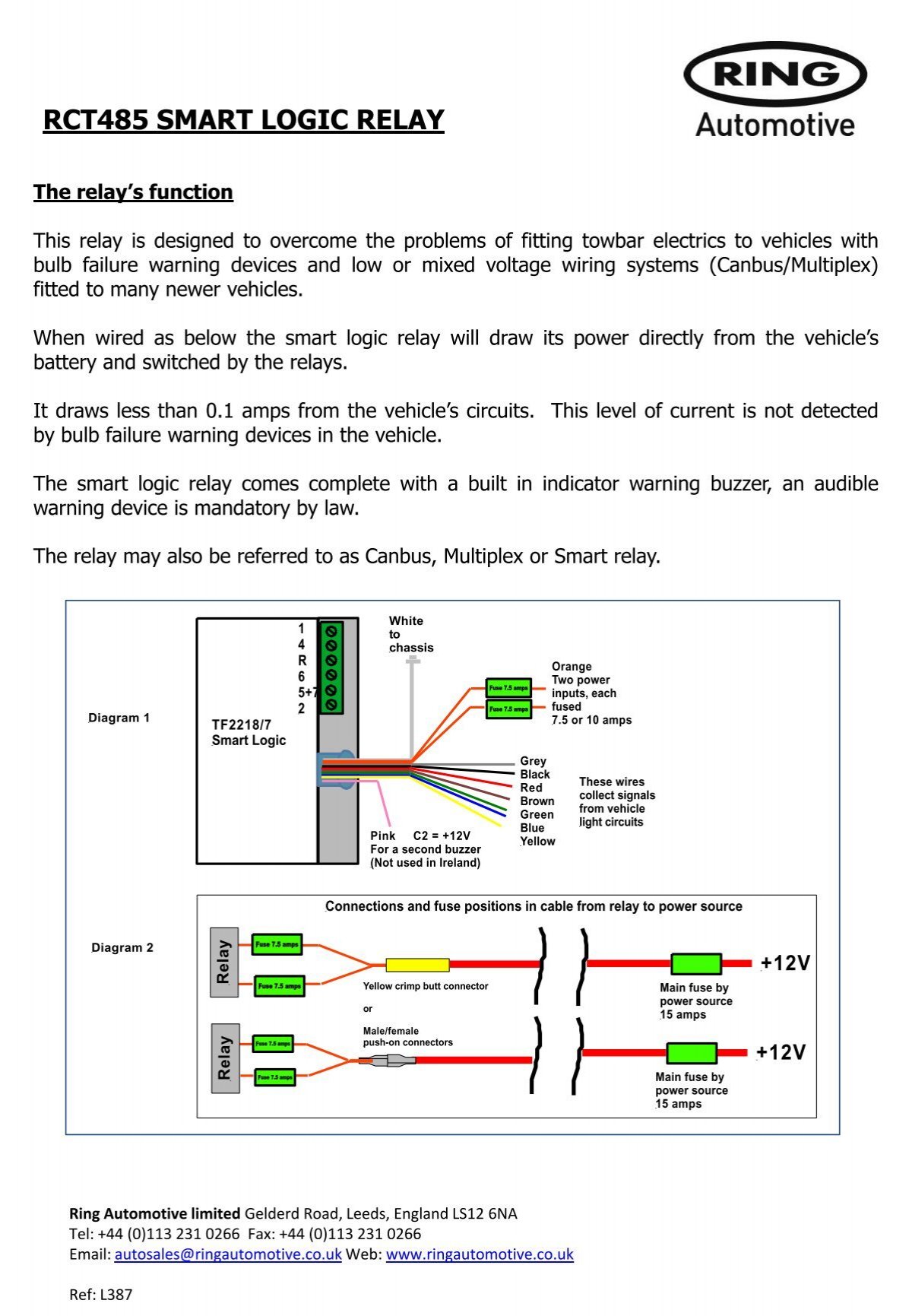
Towbar buzzer wiring diagram. Wiring diagram for 12n type 7 pin including rear mounted audible buzzer for most cars that do not require bulb failure bypass relays. The towbar buzzer relay consists of two monitoring circuits one circuit for each side of the vehicle. A buzzer is often mounted on such a module and therefore should a flasher on the vehicle fail when towing a double flash rate will be created even though the buzzer will still be sounding. If the towing vehicle has a canbus wiring system or bulb failure system then you should fit rct480 7 way smart relay. This will conform to the law. Towbar 12n wiring general guide before you start.
It shows the components of the circuit as simplified shapes and the capacity and signal connections along with the devices. Towbar buzzer wiring diagram wiring diagram is a simplified conventional pictorial representation of an electrical circuit. This comes complete with an audible warning buzzer in place of the rct380 audible relay. 12 s are used for reverse lights and other lights within the trailer refrigerator etc however these have been replaced by 13 pin. Towbar wiring guides. Wiring diagram for double relay on 12s socket.
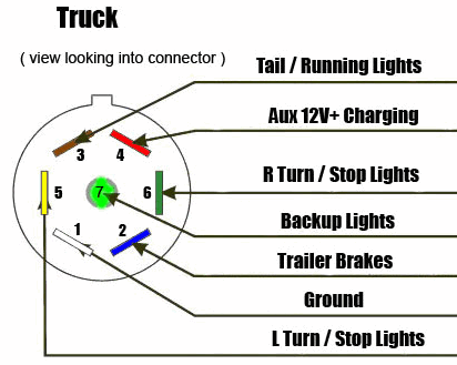
View our electrical wiring diagram guides for towbar fitting to power trailer lights and internal caravan electrics. Listed below are some basic 12n and 12s type wiring diagrams that will help in vehicle wiring for both road lights and caravan internal electrics. Listed below are some basic 12n and 12s type wiring diagrams that will help in vehicle wiring for both road lights and caravan internal electrics. The buzzer is fitted inline between the vehicles flasher circuits and the wires on the seven core cable carrying the current via the towbar socket to the trailer indicator lamps. 7 pin 12n type plugs are only used for road lighting these are the most popular however they are slowly being replaced by 13 pin plugs and below we have the difference between these plugs. Fuses engine management alarm or audio equipment may be affected.
Wiring diagram for 12n type 7 pin black socket or plug for vehicle road lights. Alternatively we are willing and able to look at any wiring problem here at our workshops. Wiring diagram for self switching relay on 12s socket. Check and test the fuses on all circuits. Locate the wiring to the rear lights of the vehicle usually on one side and select a suitable point at which to mount the audible sensor relay and make the necessary relay connections. This is because the car does not detect the flasher on the trailer.
The buzzer relay will only buzzer if a current is passing through it to the trailer lamps meaning when no trailer is attached no buzz will be made it will remain silent.


