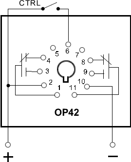
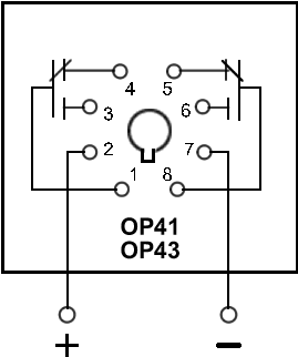
Td 8 series all date code 1442 or later. Note that the user must provide the voltage to power the load being switched by the output contacts of the time delay relay.

Sw 1466 Solid State Time Delay Relay 12v On Off Delay Timer
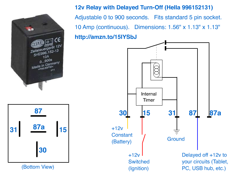
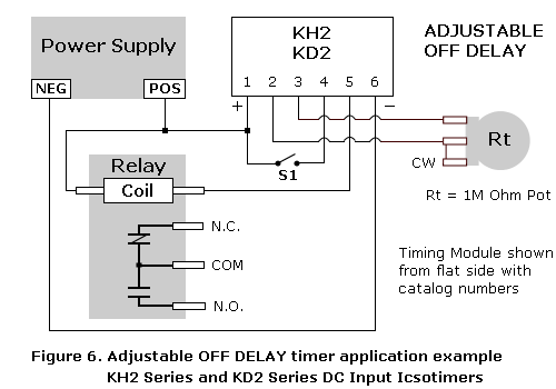
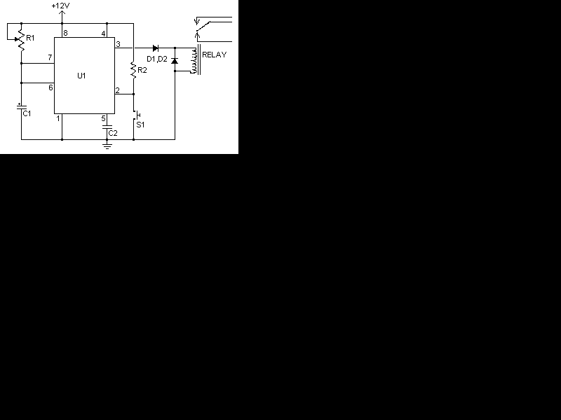
Time delay relay wiring diagram. Beuler bum waterproof 12 vdc automotive 5 pin relay connection diagram the beuler bum relay is unique being that it is a waterproof 12 volt. During the circuit design with the timer relay and variety of timer configuration questions such what. 23 connecting 10amp negative sink output timer 3. Understanding all the time delay relay functions available in multifunctional timer can be an intimidating task. If you want to start the device after a certain time by pressing the button you will use the on delay timer. A wiring diagram is a streamlined conventional photographic depiction of an electric circuit.
The following is a timing diagram of this relay contacts operation. Understanding timer delay relay function. It reveals the elements of the circuit as simplified shapes as well as the power and also signal links between the gadgets. The time relay is divided into the on delay timer and the off delay timer. The contacts of the off delay look like a single pole switch with an arrow pointing down from the switch. Series c date code 0938 or later.
Flashing light control time on time off. Td 802 td 805 td 815 td 816 td 831 td 851 series. Time delay relays uses in industrial control logic circuits. A wiring diagram is a sort of schematic which utilizes abstract pictorial signs to show all the interconnections of elements in a system. Assortment of time delay relay wiring diagram. Time delay relays are very important for use in industrial control logic circuits.
Some examples of their use include. Output loadevery time delay relay has an internal relay usually mechanical with contacts that open close to control the load. Time delay relay wiring diagram just whats wiring diagram. Instruction sheets for time delay relays. Instruction sheets for time delay relays. The off delay timer coil is labeled the same way as other loads are identified in ladder diagrams with the exception of the abbreviation of td to indicate time delay.
They are represented by the dotted lines in the wiring diagrams. Series a b date code 0937 or earlier. The bueler time delay relays are unlike the vast majority of other relays you. There are a few questions in there so i will try to address them all.
