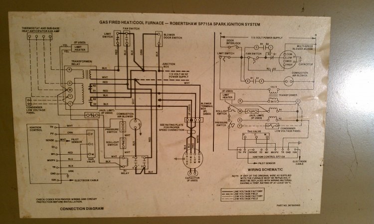
He also explained all its little foiblessnags etc. Unable to find it on forum.

4 Pole Electric Motor Wiring Diagram Diagram Base Website
Thule omni step wiring diagram. Omnistor all 12v omni steps control switch the omni step 12v is operated by means of a new design switch which perfectly compliments with the interior of modern motorhomes. Follow the wiring diagram for all electrical installation. Out with the wiring diagram and check the fuse fuse ok. Floyd turbo 25315 views. Whether you choose single slide out or double steps thule motorhome steps are made from strong yet lightweight corrugated anodised aluminium that is extremely robust. Hi all some kind soul posted a wiring diagram for an omnistep recently.
This positive supply leaves the switch at terminal 5 which is routed via a rdgn wire to the right hand end of the motor causing the step to extend. Despite regular cleaning and greasing my step has become reluctant to slide in and out. Thule advises that the step linkage should be cleaned and lubricated regularly. Repairing stuck motorhome steps kwikee steps travel supreme rv duration. Thule omni step automatic sliding step 400mm duration. Please choose the quantity you require and press the add to basket button.
Do not keep the thule step motor under tension for more than 2 3 seconds. For extra safety they also have rounded corners and antislip strips and a switch is included that can connect to a warning lamp inside your vehicle so you will never drive. On this occasion the step didnt retract. Cut the connection when the step is fully extended. 1 extend the step connect the thule step motor to a 12v dc battery. This article explains how to deal with a recalcitrant step the work should take no more than a couple of hours.
Saved it to compbut lost it when had comp probs. A positive supply from the leisure battery enters the switch at terminal 3 via a bngn wire. Swapped fuse for another 20 amp fuse to be sure still nothing. This is a genuine thuleomnistor step accessory. I tried the rocker switch but no luck. It was done in a manner even a numpty like me could understand.
The grease on the runners has attracted both dust and grit. Place the purple wire on the positive pole and the orange wire on the negative pole. I normally rely on the engine start procedure to retract the step and usually hear the step retract and check all is well with my nearside mirror. When the step has extended you must leave go of the switch or the current will increase to 14 amps. Nowadays the information on clives website may well be out of date and you would be better to provide your auto electrician with copies of the manual slideoutstep12v and manualrelayfor step12v user manual files that include a wiring diagram for the current thule product that can be downloaded from the thule website via.


