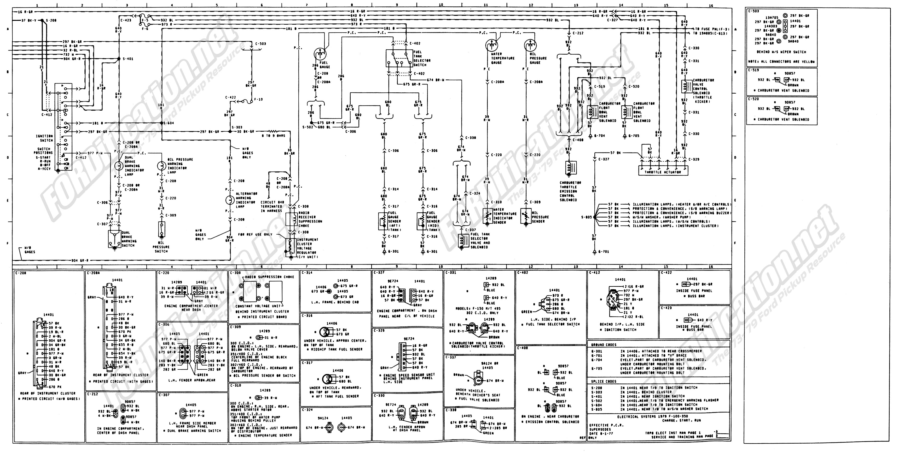
744a 3 unit 6 wires from the output cable are used to control a three section boom. By headcontrolsystem teejet 744a 3 wiring diagram architectural circuitry diagrams show the approximate places as well as interconnections of receptacles illumination and long term electrical solutions in a building.

Ag Sprayer Parts Ag Application Equipment Mid South Ag
Teejet 744a 3 wiring diagram. A wiring diagram is a schematic which uses abstract pictorial symbols to demonstrate all the interconnections of components inside a system. Also view our online catalog for all our teejet spraying products. The 744a allows for the choice of liquid filled 100 psi 7 bar or 300 psi 20 bar. Teejet 744a 3 wiring diagram whats wiring diagram. The 3 rpm is the most popular and opens the valve to the maximum flow in about 6 seconds for the rl valve and about 10 seconds for the pr valves. Other teejet b series regulating valves are plug n play compatible with all these kits if ordered with the 01ccs connector option mid tech part number old ssco number 744a 3 switch console harness boom valves regulating valve 100 psi gauge 300 psi gauge sole noid ball valve no e 144a 3 144p 3 244 butterfly 344 2rl ball kit part.
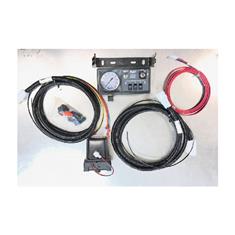
The console features a lighted pressure gauge for night use and heavy duty switches with led indicators. Variety of teejet 744a 3 wiring diagram. The 6 rpm motor cuts those times in half. When using a 344aec ball valve connect to the white wire. Dultmeier sales will be closed thursday november 22nd and friday november 23rd in observance of thanksgiving. Teejet repair parts diagrams from dultmeier sales.
English din cable cable 15 05 meter din cable 5 15 meter din cable 10 3 meter din cable 20 6 meter din cable permanent etched marking with. Other teejet b series regulating valves are plug n play compatible with all these kits if ordered with the 01ccs connector option mid tech part number old ssco number 744a 3 switch console harness boom valves regulating valve 100 psi gauge 300 psi gauge solenoid ball valve none 144a 3 144p 3 244 butterfly 344 2rl ball kit part. It shows the elements of the circuit as streamlined shapes and also the power and also signal links between the tools. 90 50149 744a series 90 50161 744a series 90 50163 744a series 90 02439 744a series radion 8140 automatic. Adjoining cord courses might be shown about where specific receptacles or fixtures should get on an usual circuit. Orange right yellow center green left connect to 144a valves.
A wiring diagram is a streamlined conventional photographic representation of an electrical circuit. Chapter 1 introduction the 744a sprayer control provides manual spray control in a compact battery package.


