Teejet technologies has developed a special ball that allows the valve to start regulating earlier thus extending the regulating range. Variety of teejet 744a 3 wiring diagram.
.jpg)
Used Industrial Surplus Equipment Buyer Amp Seller
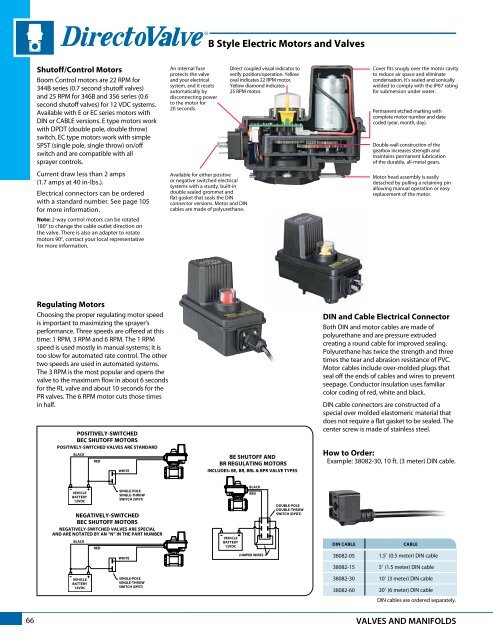
Teejet 344 wiring diagram. At teejet technologies we recognize that agriculture is an essential business and are therefore taking all necessary steps to remain open and to ship each and every customer order as quickly as possible. A wiring diagram is a streamlined conventional photographic representation of an electrical circuit. Teejet ball valve wiring diagram 344 series 3 way shutoff valve w 1 connections teejet farmer. Teejet repair parts diagrams from dultmeier sales. Multilingual metric teejet part 98 01173 en us english usa teejet part 98 01162 cs czech česky teejet part 020 033 da danish dansk teejet part 020 033dk and 98 01178da de german deutsch teejet part 020 033 es es spanish español teejet part 020 033 fr french français teejet part 020 033. Teejet 344 series electric shutoff 3 way valve 1 thread ec motor.
Also view our online catalog for all our teejet spraying products. It shows the components of the circuit as simplified shapes and the talent and signal connections in the company of. Dultmeier sales will be closed thursday november 22nd and friday november 23rd in observance of thanksgiving. We will provide a further update if we expect delayed shipments for any reason including government imposed restrictions on our operations. Teejet ball valve wiring diagram wiring diagram is a simplified up to standard pictorial representation of an electrical circuit. It shows the elements of the circuit as streamlined shapes and also the power and also signal links between the tools.
Centerline centerline 220 user guide. Dultmeier sales will be closed tuesday december 24th at 12pm and all day wednesday december 25th. The 344 series has many options to provide ideal performance. These options include the choice of either a polypropylene or stainless steel ball to complete the stainless steel stem the option for either an e or ec series motor as well as cable or din electrical connections. Plumbing diagram centrifugal pump and self cleaning strainer to 744a controller throttling valve throttling. Plumbing diagram diaphragm pump boom 1 boom 2 boom 3 boom valves 1 3 regulating valve gauge tee pressure relief valve tank shut off line strainer diaphragm pump throttling valve to 744a controller jet agitatior figure 4.
The flow from the valve starts 10º earlier than a regular r. This special ball valve also increases flow and the linear characteristic of the valve during the first ¾ of the valve cycle.


.jpg)


