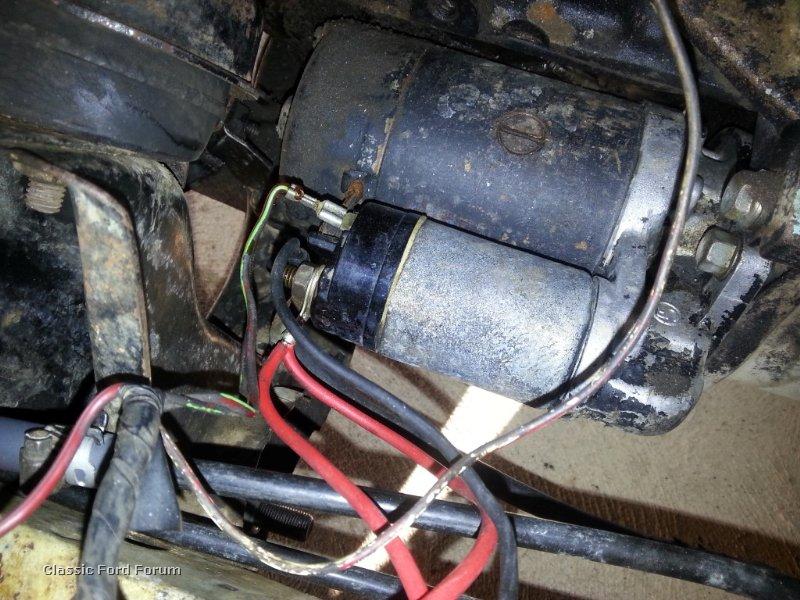
A typical starter solenoid has one small connector for the starter control wire the white connector in the photo and two large terminals. To check out a wiring diagram first you need to recognize what basic components are included in a wiring diagram as well as which pictorial icons are used to represent them.

Holden 308 Starter Motor Wiring Diagram Diagram Base Website
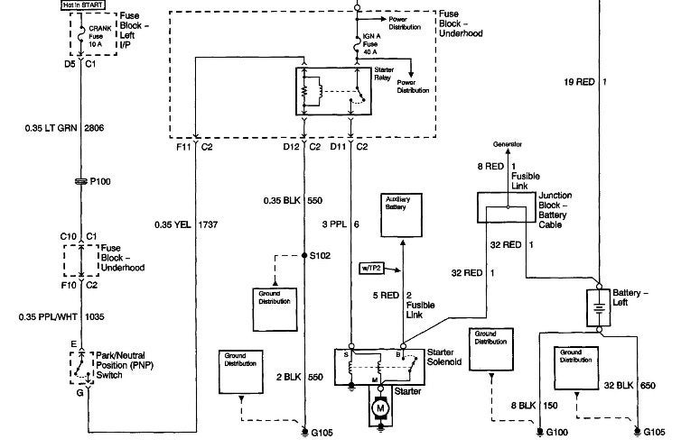
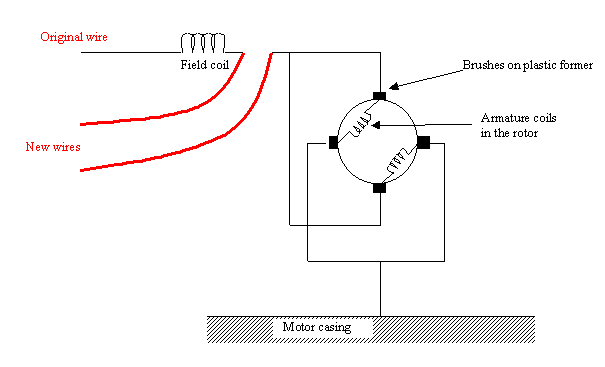
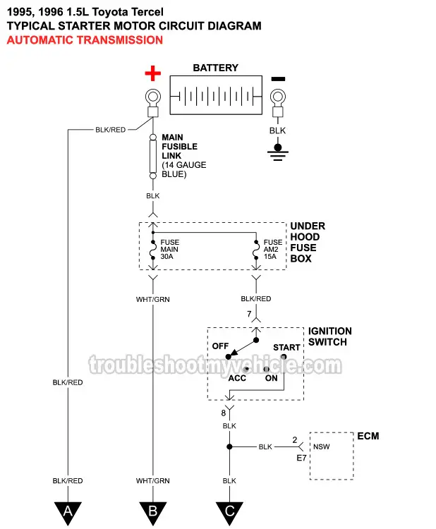
Starter motor wiring diagram. The common components in a wiring diagram are ground power supply cord and connection outcome gadgets switches resistors reasoning gateway lights etc. It reveals the parts of the circuit as simplified shapes and the power and signal links between the gadgets. Wiring diagram will come with numerous easy to stick to wiring diagram instructions. Square d motor starters wiring diagram sq d motor starter wiring diagram square d 3 phase motor starter wiring diagram square d 8536 motor starter wiring diagram every electric structure is composed of various distinct pieces. Merely ignore the control wiring in red. Wiring diagrams bulletin 609 manual starters are operated by.
Star delta starter motor control with circuit diagram in hindi starter motor wiring diagram. Each part should be placed and linked to different parts in specific way. Wiring diagrams ww introduction this booklet has been prepared as a guide to some of the useful ways allen bradleys manual and magnetic across the line starters. A wiring diagram is a simplified traditional photographic representation of an electric circuit. If not the structure wont work as it ought to be. One for the positive battery cable and the other for the thick wire that powers the starter motor itself see the diagram below.
In north america an induction motor will typically operate at 230v or 460v 3 phase 60 hz and has a control voltage of 115 vac or 24 vdc. The wiring diagram is a little unclear in the box and i dont want to burn the magnetic starter is furnas the motor is a baldor t 5 hp 3wiring instructions for magnetic starters important if the compressor has a factory mount ed magnetic starter the starter has been wired to the pressure switch and motor. Line 1 l1 t1 motor 1 l1 hot 240v or neutral 120v line 2 l2 t2 l3 t3 motor 2 l2 hot 120v or 240v manual starter. Two speed manual motor starter is designed for starting protecting small single phase two speed ac fan motors. It really is supposed to help all of the average consumer in creating a correct method. A motor starter is a combination of devices used to start run and stop an ac induction motor based on commands from an operator or a controller.
Collection of single phase motor starter wiring diagram. The starter solenoid works as a powerful electric relay. To ensure that the starter can stall automatically and the starter circuit not connected after the engine starts some cars adopt the compound relay circuit with safety driving protection. These guidelines will probably be easy to comprehend and apply. The security starter relay controlled car starter wiring diagram is as shown in the. Security starter relay controlled car starter wiring diagram.
.jpg)


