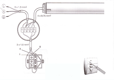
Universal rts interface ii. Cabling arrangements are shown in the diagram.

Building A Somfy Controller With Arduino And Vera Wiring The
Somfy rts wiring diagram. Electric operated wiring diagram somfy electric motor pricing. Symbols that represent the constituents within the circuit and lines that represent the connections with shod and non shod. Wiring rules your somfy rts motor can be supplied to the left or right hand side. Somfy blind motor wiring diagram whats wiring diagram. According your wiring diagram fibaro input switch is ac. We are here to help.
Connect a single somfy urtsi ii for rs control motor. Rs232 to rts 1810686 db9 female rs232 input m a d e i n u s a s o f y 7 4 3 0 f r a n c e r 2 8 p m 0. Por la presente somfy declara que el aparato cumple las exigencias esenciales y el resto de disposicio nes pertinentes de la directiva 19995ec. N o d e i. Respect the electrical standards in force as well as the following points. Request an online quote or use our selection assistant to find your product.
Wiring diagrams are made up of two things. Non somfy motor drape motor with rj input for example via somfy rts transmitter. 0 1 e db9 female rs232 input rs232 for multilink 1810602 sonesse 30 rs485. Signal somfy rj45 gnd rs485 rs485 8 s t30 m or 1 red 2 black. Podrá encontrar una declaración de conformidad en la página. 227 wiring diagram 1.
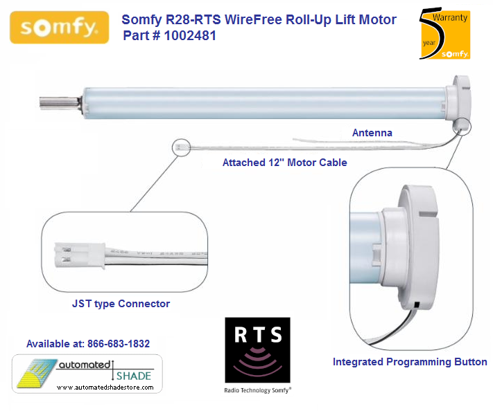
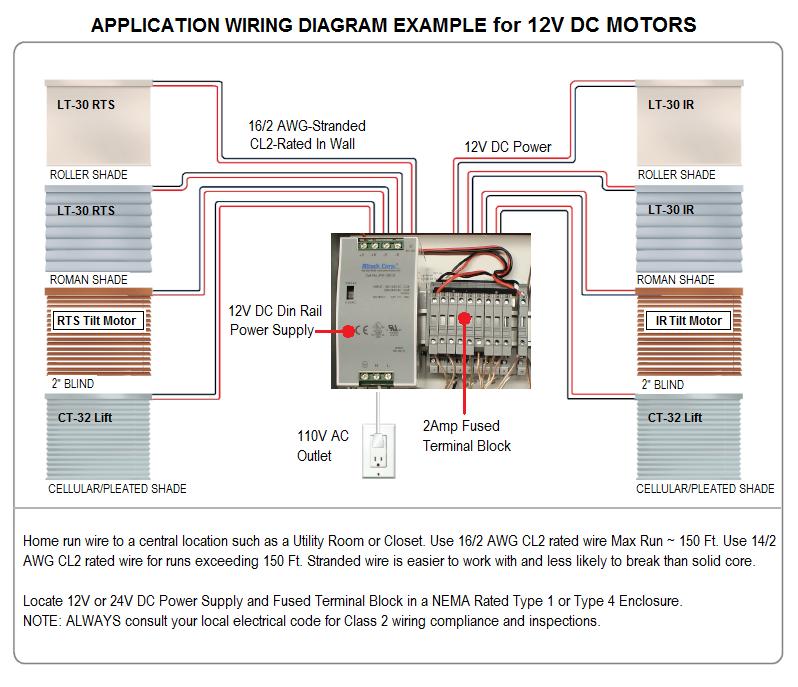
The eolis receiver rts is compatible with all standard somfy motors. Find out our products manuals and frequently asked questions. Connect high voltage wires according to the wiring diagram on the next page. A wiring diagram is a type of schematic which uses abstract pictorial symbols showing all the interconnections of components inside a system. The led of the rts control lights but the motor. Make sure to use included watertight strain relief fittings to maintain the weatherproofing of the enclosure.
8 a i p 3 0 2 n m 2 4 v d c s o n e s e 3 0 r s 4 8 5 5 0 6 3 2 8 1 x 0 1 d 0 6. 3 check the good wiring of the motor and the eolis receiver rts. If used the rts sensor should be placed close to the awning or shading system to make sure the wind speed or sun intensity is measured at the product. It can be plugged into a socket or hard wired into a fused spur. If you have more than one blind to a window each one requires an individual switched socket or a fused spur in order to isolate the.


