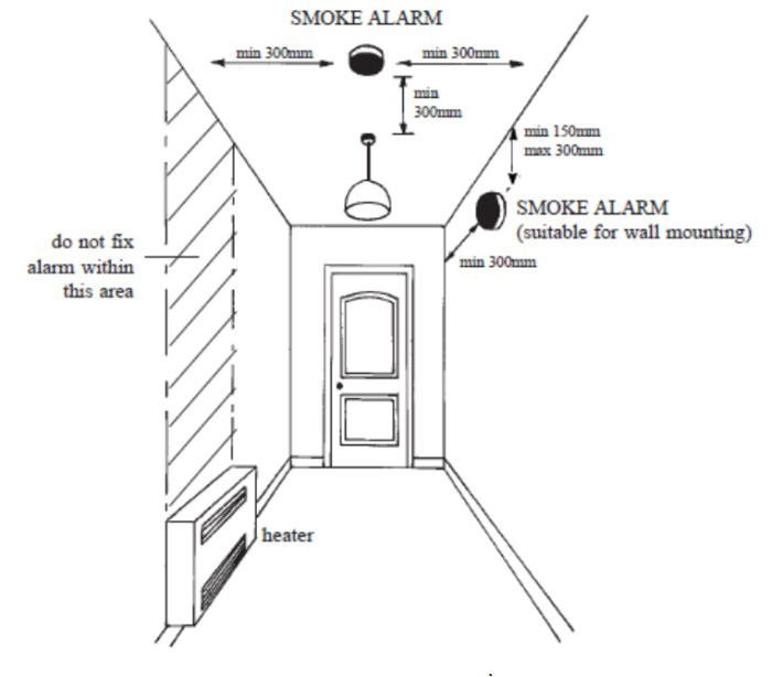
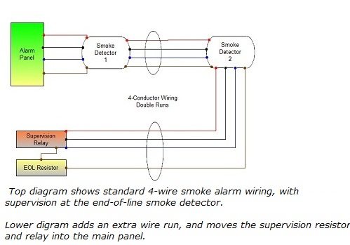
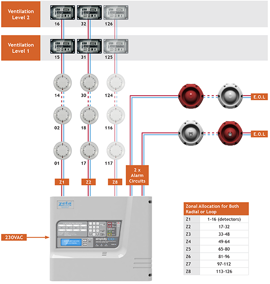
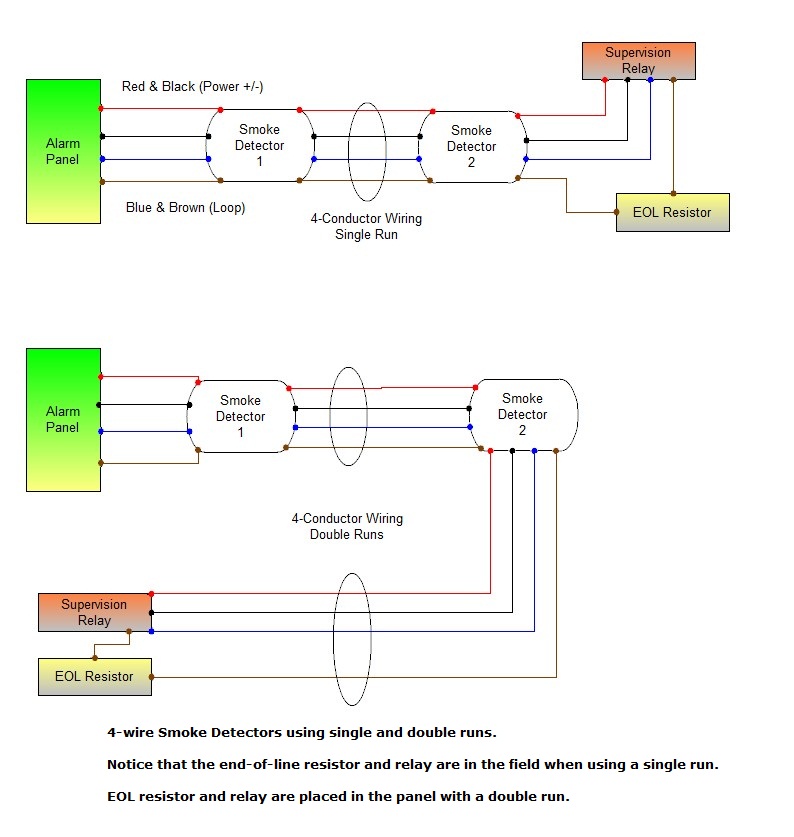
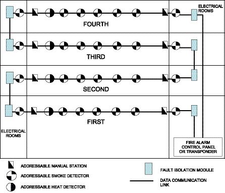
Know the basics of smoke detector wiring and learn how these detectors are connected together in a series. In england the minimum guide for smoke alarm positioning to meet building regulations is as follows.

Alarm Siting Brk
Smoke detector wiring diagram uk. Basic electricians pouch of hand tools non metal step ladder and a voltage tester. Locate the thermoptek smoke alarm close to bathrooms or showers as it can be susceptible to nuisance alarms from steam. White black and yellow. Wiring the smoke detectors is fairly straightforward for an experienced diyer or a professional electrician. Truly we have been realized that how to wire smoke detectors in series diagram is being just about the most popular topic at this time. All dwellings should be provided with an alarm system to at least grade d category ld3 position optical or multi sensor mains powered alarms with an integral backup power supply within the escape routes of the property ie.
The alarm base plate is designed to be permanently mounted using its own builtin terminal block to connect it to the mains. The wiring suggests that this is the secondthird etc interconnected smoke alarm on the circuit with the yellow cable acting as the switch live. Wiring diagrams are included in the instructions supplied with all alarms but here are a few basics. How to install a hardwired smoke alarm ac power and alarm wiring intended for how to wire smoke detectors in series diagram image size 715 x 365 px. Install heat alarms on a wall. All mains powered alarms and accessories need a mains supply that is taken from a permanent live feed for example a lighting circuit.
Fire detector manual fco dec10 automatikprodukter 1 general overiew 2 description 21 control mode 22 sensor 3 installation 31 mounting instructions 32 installation 4 electrical connection 41. Wiring smoke detectors electrical project skill level. First old work electrical ceiling boxes are installed at appropriate spots where the smoke detectors will be installed. All smoke alarms are slightly different in set up so check the instructions for interconnected smoke alarms and follow the wiring diagram. Dcp communications protocol allows system components dcp sensors aie ea alg v aca v acc v alk v aln v atj ea and atg ea bases and modules to be used concurrently on a systems slc signaling line. The smoke detectors wiring harness has two parts.
This power source can be a circuit. Wiring diagram photoelectric smoke detector model no. You should be able to see three wires coming out of the harness. Fire alarm control panel compatibility is required for dcp products. Wiring connection 5 commissioning 51 calibration 52 manual calibration 521 zero point 522 gain 523 calculation of control voltage 53. Then a 2 wire cable is run from the power source to the first smoke detector.
Mains powered smoke heat alarms radiolink radiolink and smartlink wireless interconnection. The fixed wires and the wires that protrude from the harness.


