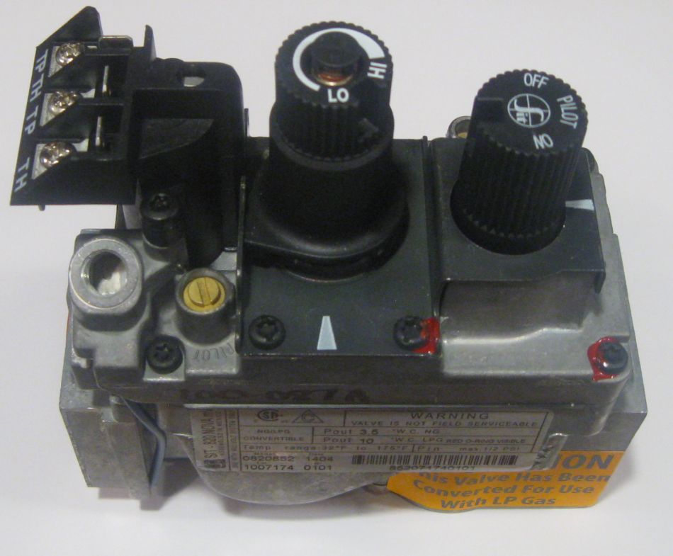
820 nova is a multi functional control with ther moelectric flame supervision device single con trol knob off pilot on restart interlock servo controlled pressure regulator onoff electric solenoid. For propane version click here propane sit quick dropout gas valve natural gas 30 turndown 16 35 wc 38 inlet outlet requires thermopile and thermocouple for operation not for vent freecross referenceastria ihp.

How To Test Your Main Control Valve Www
Sit 820 nova wiring diagram. Fl is the inlet. Installing the gas line. 820 nova mv family code 820 multifunctional gas control with single operating knob off pilot on thermoelectric flame supervision device restart interlock servo pressure regulator manual adjustment of the outlet pressure automatic shut off valve and step opening device optional. Gas fireplace repair wont work start or light piezo ignitor spark igniter duration. The right knob controls the manifold pressure to the burners and is labeled hilo. This one covers the thermopile wiring on the gas fireplace.
Refer to section 5. Adamdiy recommended for you. H5942 05 0710 0111 37526 h2825 13m8801 h165701 43k0701 43k0701 h6209 h1657. Sit nova 820 millivolt valve note. A step opening ignition device can be fitted on request. Sit nova 820 gas control and pilot15 installing onoff wall switch15 section 5.
The 820 nova millivolt combination gas control is an onoff gas valve suitable for use with gas fireplaces gas log sets. Thermocouple millivolt check symptom pilot light will not hold thermocouples have a maximum output of 25 to 30 millivolts. The left knob controls the onpilotoff functions. Before trouble shooting the gas control system be sure external gas shut off is in the on position. Installing the gas line for details on the gas connection and access. Sit 820 nova mv gas control valve sit 820 nova mv gas control valve the 820 gas control valve is shown below in figure 27.
Nova sit valves 1 thermocouple millivolt check 2 safety magnet testing 3 thermopile millivolt check 4 circuit millivolt check 5 valve operating head test. With reference to the schematic blocks in fig. Never connect valve to line voltage. Before doing any gas control service work remove glass front. This video is part of the heating and cooling series of training videos made to accompany my websites. Millivolt version wiring diagram 6 4 2 8 10 12 e a p i lo t tp th tp th room thermostat pilot burner millivolt plus version wiring diagram warning.


