Wellborn collection of single phase motor starter wiring diagram. Single phase capacitor motor wiring diagrams wiring diagram single phase motor wiring diagram with capacitor.
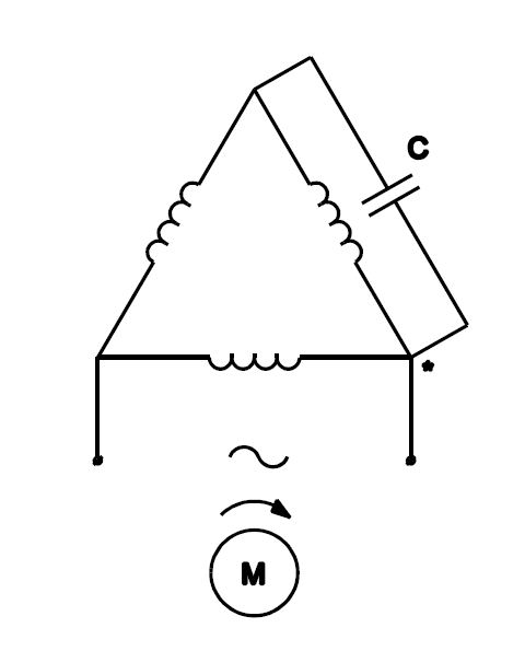
How To Use Three Phase Motor In Single Phase Power Supply
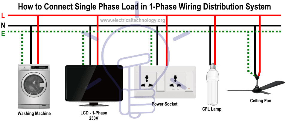
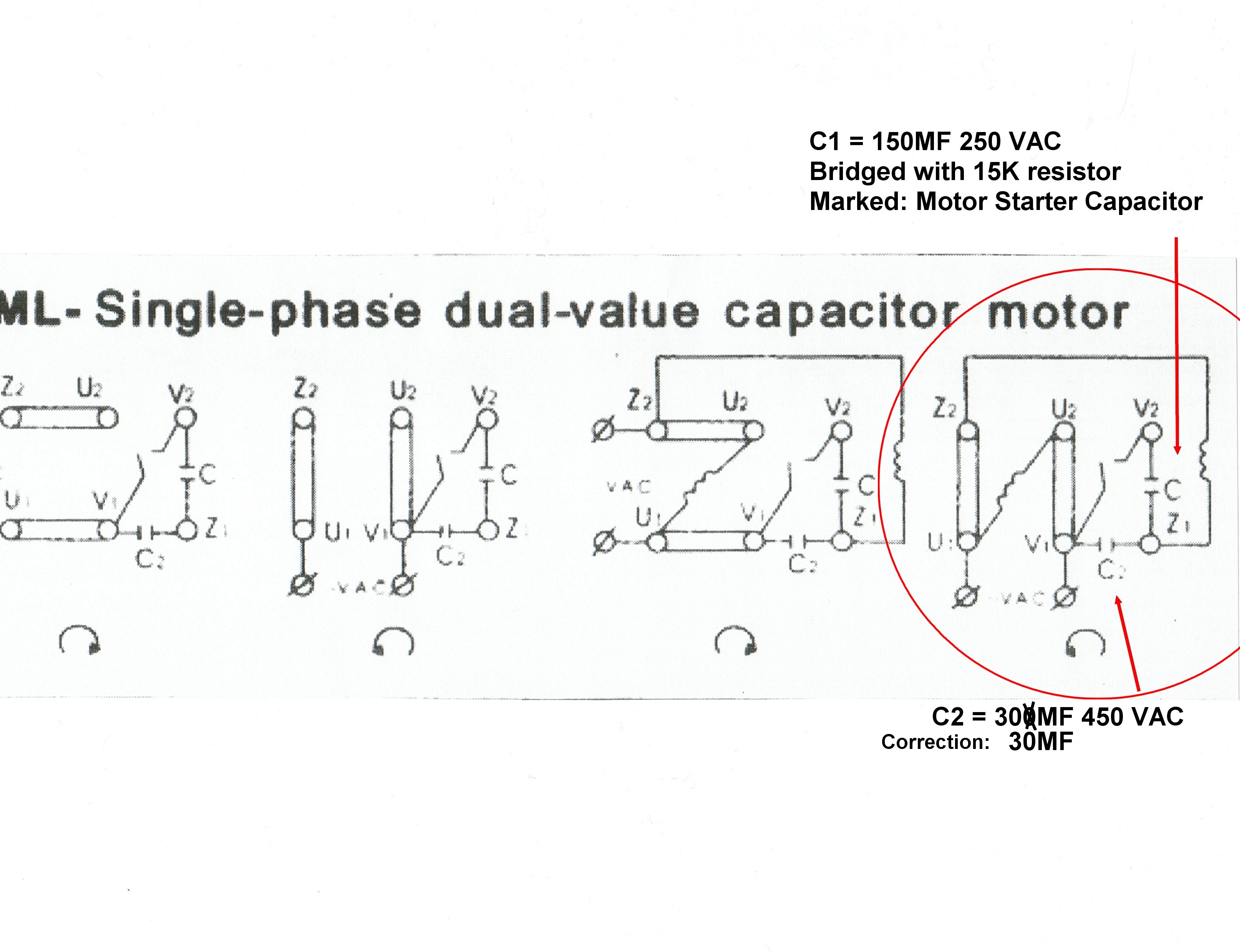
Single phase wiring diagram. It makes the process of building circuit simpler. I have compiled a list of single phase electric motors and their wiring diagrams below. Only power conductors should be connected through the circuit breaker. Strip the wire ends with a wire stripper and fasten them together with a wire nut. Single phase motor internal wiring diagrams. Never make ground connections through a circuit breaker.
A wiring diagram is a simplified traditional photographic representation of an electric circuit. It reveals the parts of the circuit as simplified shapes and the power and signal links between the gadgets. Notice that the output of the. January 6 2020 by larry a. Capacitor start capacitor run induction motors are single phase induction motors that have a capacitor in the start winding and in the run winding as shown in figure 12 and 13 wiring diagram. Watch single phase electricity explained wiring diagram energy meter world entertainment on dailymotion.
The ground terminal should be a green screw or possibly a green wire. Input power wiring diagrams option c input power wiring diagrams option c smart series the 240 volt single phase connection only uses two power lines plus ground. The above diagram is a complete method of single phase motor wiring with circuit breaker and contactor. This video will take a step by step look at the process of installing and connecting a home single phase electricity meter. Single phase energy meter wiring diagram and connection in tamil. Single phase three phase wiring diagrams 1 phase 3 phase wring the star delta y δ 3 phase motor starting method by automatic star delta starter with.
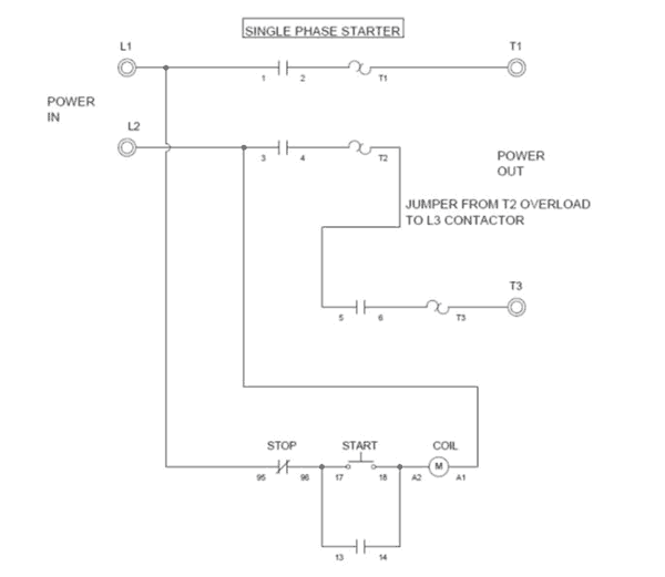
In the above one phase motor wiring i first connect a 2 pole circuit breaker and after that i connect the supply to motor starter and then i do cont actor coil wiring with normally close push button switch and normally open push button switch and in last i do connection between capacitor start motor and contactor. This type of motor is designed to provide strong starting torque and strong running for applications such as large water pumps. The diagram provides visual representation of a electric arrangement. At the bottom of this post is also a video about dc shunt motors. Connect the ground wire from the switch to the ground terminal in the wiring box. Where can i find single phase electric motor wiring diagrams.
On the other hand this diagram is a simplified variant of this arrangement.

