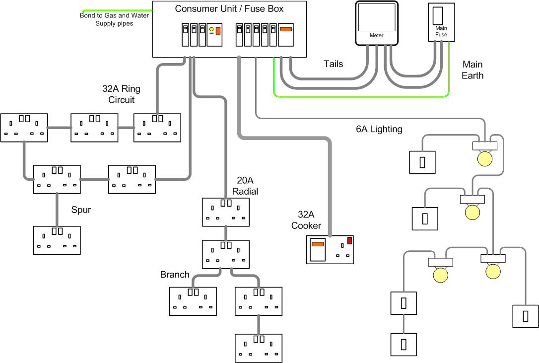
Shower rcd wiring diagram. More electrical tips and diagrams wwwaboutelectricitycouk like subscribe and dont skip the ads shopping.
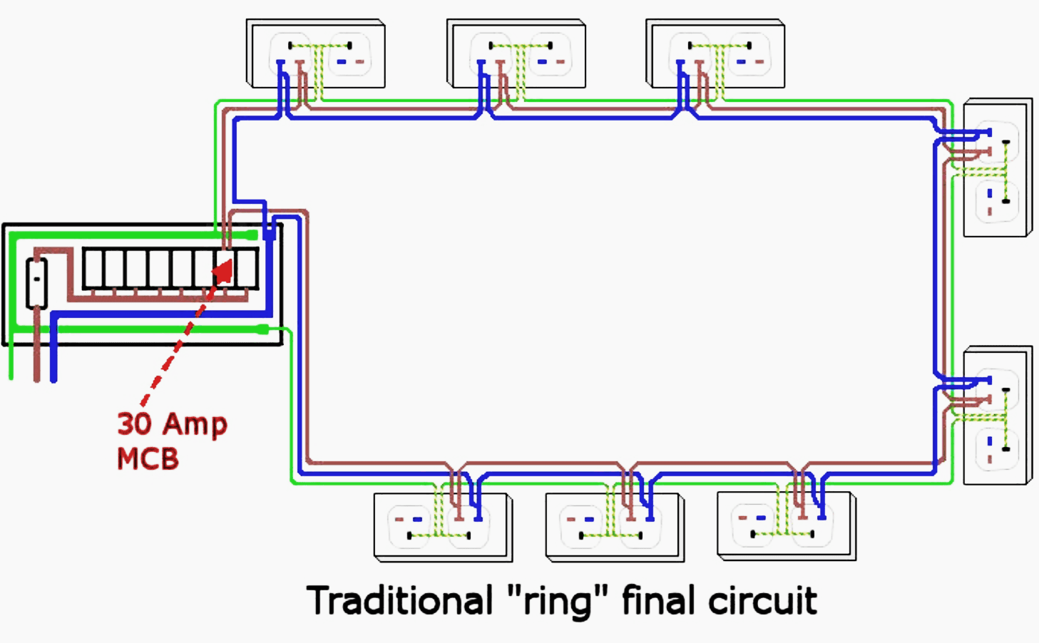
Good Consumer Unit Design And Low Electric Fields In The House
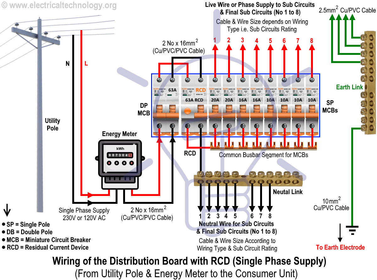
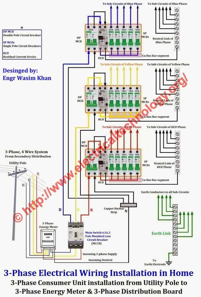
Shower rcd wiring diagram. We want to know where the supply goes into the unit and where the load comes out ie. Here is the rcd wiring diagram in which i install the main distribution board. Advice on fitting a pull cord switch replacing a pull cord switch or replacing the cord. In this diy guide we will show you how to repair a bathroom light pull cord switch or 45amp shower pull cord switch. The installation of rcd is too simple in single phase wiring main board. 17112018 17112018 7 comments on shower rcd wiring diagram.
How to go about wiring a shower or bathroom light pull cord switch. Find out how to wire residual current device rcd in garage shed consumer unit. An electrical shower is one of the largest consumers of electricity in the home of a mcb and also an rcd. Wherever possible showers should always be protected by an rcbo this is a device that does the job of both an mcb to provide overload protection and short circuit protection and an rcd to give earth fault protection. I told a long time served electrician about my problem of adding an rcd to a shower circuit and no form of isolation of the tails which presently. In the above distribution diagram i shown the wiring installation of double pole mcb circuit breaker rcd circuit breaker single pole mcb breakers voltmeter light indicator.
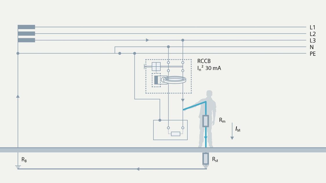
Rcds httpsgoogl9bxuvp split load consumer unit httpsgoogl2aepr1 garage consumer unit httpsgooglb8rdde wiring diagrams schematics. If the shower is a fully thermostatically controlled unit then a diversity factor may be assumed of not less that 80. Hiya chaps just trying to install a shower rcd unit to an old fashioned consumer unit however mk didnt bother to include a wiring diagram. Due to the nature of pull cord switches they can wear out quite fast. How to wire rcd residual current device. In this single phase home supply wiring diagram the main supply single phase live red wire and neutral black wire comes from the secondary of the transformer 3 phase 4 wire star system to the single phase energy meter note that single phase supply is 230v ac and 120v ac in usthese two lines line and neutral from energy meter are.
