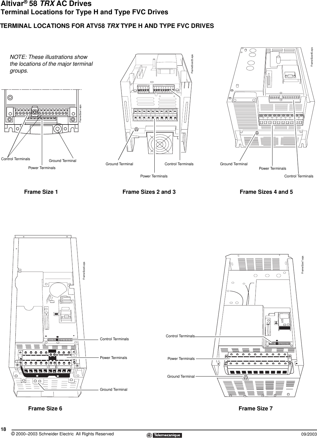
Control wiring enables complete control of your installation energy management system programmable logic controllers building management system internet. Refer to the wiring diagram page 54 for dip switch settings each control contact must be suitable for a 5 v dc low energy circuit.

Acb Wiring Wiring Diagram
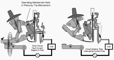
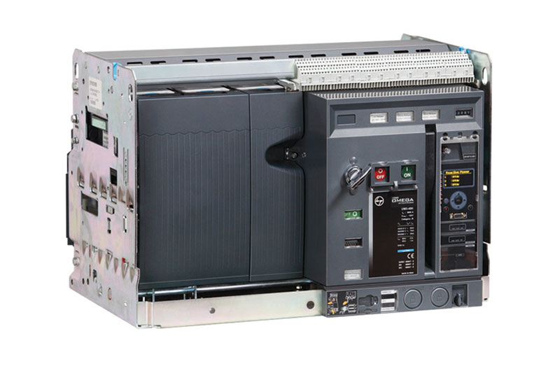
Schneider acb wiring diagram pdf. Overload testing internal wiring diagram of new dn release ct r phase ct y phase ct b phase t1 m1 t2 m2 t1 m1 t2 m2 t2 m1 t2 m2 s o l bime xxx sc. Internal connections of the dn release with ct is shown in the following diagram. 16 electrical auxiliaries tripping notification. Masterpact nw drawout circuit breakers low voltage power circuit breaker insulated case circuit breaker iec rated. Electrical diagrams 28 discovering masterpacts accessories 30 micrologic control units 30 indication contacts 31 auxiliaries for remote operation 33 device mechanical accessories 36 chassis accessories 38 inspecting and testing before use 40 initial tests 40 what to do when the circuit breaker trips 41 maintaining masterpact performance 42. Schneider electric available only from schneider electric.
Wiring diagram book a1 15 b1 b2 16 18 b3 a2 b1 b3 15 supply voltage 16 18 l m h 2 levels b2 l1 f u 1 460 v f u 2 l2 l3 gnd h1 h3 h2 h4 f u 3 x1a f u 4 f u 5 x2a r power on optional x1 x2115 v 230 v h1 h3 h2 h4 optional connection electrostatically shielded transformer f u 6 off on m l1 l2 1 2 stop ol m start 3 start start fiber optic. Programmable engine exerciser connection if provided refer to page 53 load disconnect feature connections see wiring diagram refer to page 54 for dip switch settings figure 1 2. 1 masterpact nt. Acb is not tripping in case of overload or short circuit fault probable cause a connection between ct. Masterpact circuit breakers are available in square d or schneider electric brands. Nec and other local wiring codes.
9 part of isobar.


