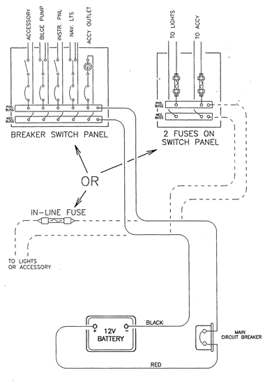
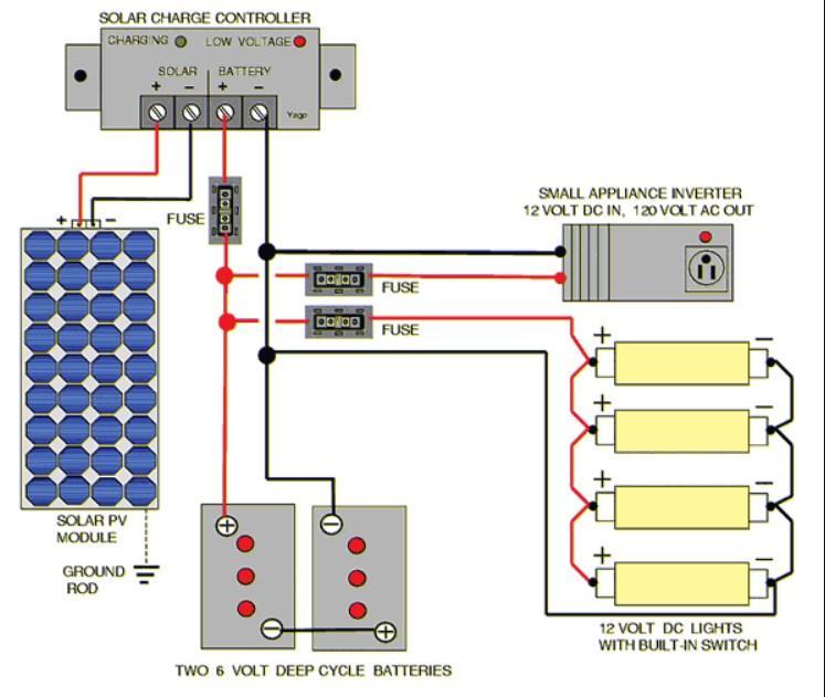
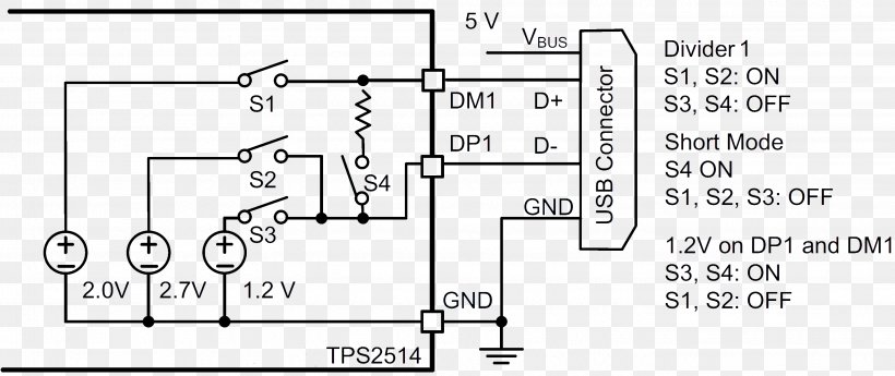
You may have heard them very often but they vary each other slightly. In the schematic straight solid lines indicate wiring and connections between various parts.
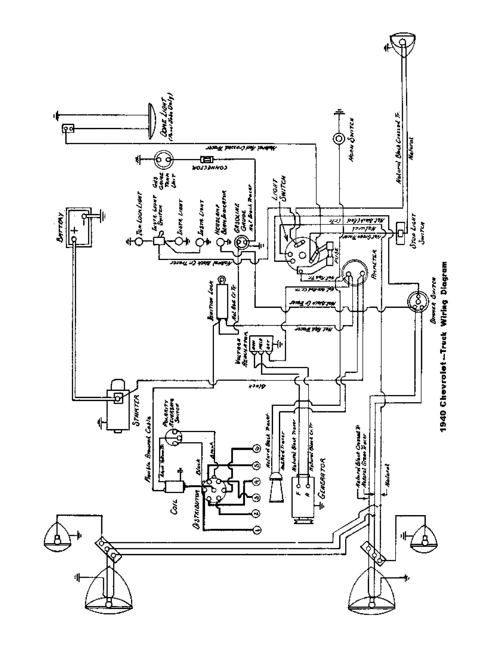
Chevy Wiring Diagrams
Schematic wiring diagram. With the light at the beginning middle and end a 3 way dimmer multiple lights controlling a receptacle and troubleshooting tips. Short zigzag lines are resistors. Symbols that represent the components in the circuit and lines that represent the connections between them. Wiring diagrams show how the wires are connected and where they should located in the actual device as well as the physical connections between all the components. Welcome to the scheme it free online schematic and diagramming tool digikey electronics scheme it project. Capacitors are represented by short parallel lines that may be straight or curved.
A schematic diagram for an electronic circuit can be a helpful guide to identifying components. Wiring diagrams are made up of two things. It is usually used to communicate or intended to convey the connections and working of the circuit to other engineers. Our products are under continuous development. Nets with the same name are assumed to be connected even though there isnt a visible wire connecting them. A wiring diagram is a type of schematic that uses abstract pictorial symbols to show all the interconnections of components in a system.
When this is determined to have a significant bearing on this manual a new edition of this file will update the changes. Scheme it is a free online schematic drawing tool that will allow you to produce professional looking schematic diagrams add corresponding part numbers and share your schematic with others. Vehicles produced after this publication may have different specifications and repair methods. A schematic shows the plan and function for an electrical circuit but is not concerned with the physical layout of the wires. Names can either be written directly on top of the net or they can be tags hanging off the wire. Wiring diagrams to assist with electrical interface.
Schematics circuit diagrams wiring diagrams electrical diagrams are commonly used in engineering diagrams. Wiring diagrams and electrical schematics f 250350 pickup in bed tank wiring harnesses and connector layout in bed lpa fuel tankfuel tank underhood harness can harness rear frame harness in tank harness solenoid harness in bed fuel tank jumper ftpt jumper harness 27 24 21 1 6 fuel tank 9 4 1 4a 4b 9 41 30 47 15 27 8 11 23 9 5 1 1 35 51 55 gnd. A schematic diagram shows the components and their values and connections in an understandable manner. Refer to this page to learn the differences between schematic diagrams and circuit diagrams. Sometimes to make schematics more legible well give a net a name and label it rather than routing a wire all over the schematic. Wiring diagrams for 3 way switches diagrams for 3 way switch circuits including.
A schematic diagram is a circuit which shows the connections in a clear and standardized way. This article illustrates the differences between schematic diagrams and circuit diagrams and it may benefit you a lot in identifying the components of an electric system tracing a circuit and even fixing electrical.


