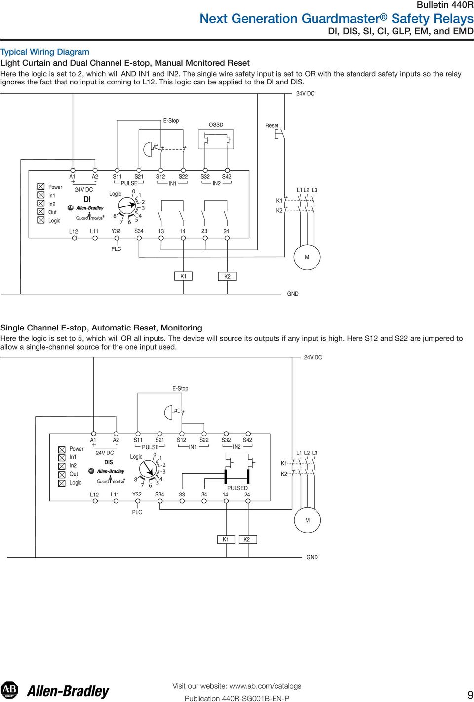
Next generation guardmaster safety relay gsr notes for example wiring diagrams note 1 in the wiring diagrams that are shown in this publication the type of allen bradley guardmaster device is shown as an example to illustrate the circuit principle. Figure 1 output load capability using interposing relays s11 s12 s21 s22 a1 13s34 a2 l11 14 23 24 33 cr1 cr2 41 y32 34 42 gsr ci 440r s13r2 reset 0.

Sick Safety Relay Wiring Diagram
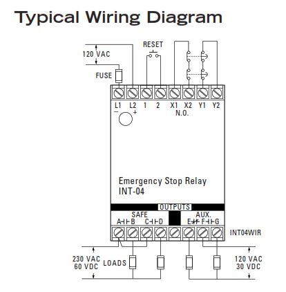
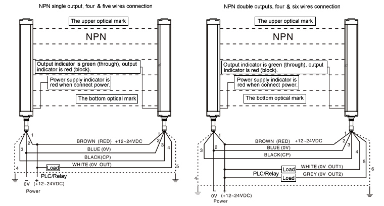
Safety relay wiring diagram. Each component ought to be placed and connected with other parts in particular way. Allen bradley safety relay wiring diagram allen bradley guardmaster safety relay wiring diagram allen bradley safety relay wiring diagram every electric structure consists of various distinct pieces. Timing is the other fault detection method safety relays use. When the load exceeds the rating of the safety relay interposing relays can be used as shown in figure1. Wiring diagram and logic circuit for 700 zbr520 and 700 zbr100 figure 5 safety relay operating principle. For wiring the safety relay g1501s.
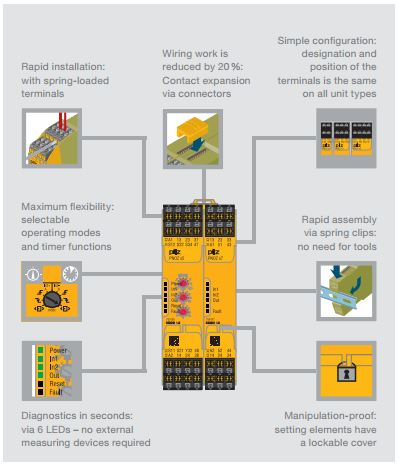
If automatic start is set bear in mind that the safety con tacts will switch immediately after the power supply is connected. With this kind of an illustrative manual you are going to be capable of troubleshoot stop and total your assignments without difficulty. By measuring flow of current the safety relay checks for welded contact sets and wire breaks. Read this document and the documents listed in the additional resources section about installation configuration and. E to din en iso 13849 1 s il 3 to d ne 61508 category 4 to en954 1 we reserve the right to make alterations without prior notice ifm electronicgmbh date. Every safety relay has limitations on the amount of current the relay can switch or carry.
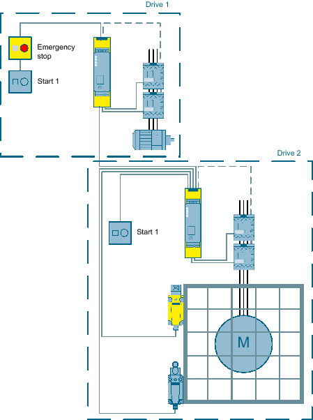
If monitored manual start is set the start button must be opened after wiring. This is all done with timing. If not the structure will not work as it should be. For special applications the choice of device type is based on the suitability of. 7 to set the starting behavior. The cr30 safety relay performs the logic that monitors the interlock and the drive and allows access to the hazard under safe conditions.
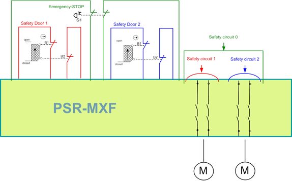
Safety relays check and monitor a safety system and either allow the machine to start or execute commands to stop the machine. 50 msec max legend 0 1 8 safety relays estop open. A safety relay detects wire breaks and faulty contactorsactuators by sending out electrical pulses through the wiring. 220307 page 2 of 15 rqwhqwv 3djh 6723 33721. Wire the start circuit according to fig. Single function safety relays are the most economical solution for smaller machines where a dedicated logic device is needed to complete the safety function.
Allen bradley safety relay wiring diagram you will want a comprehensive professional and easy to understand wiring diagram. Safety relays are becoming a popular component in safety systems due to increasing regulations and attempts to safeguard operators from hazards. Connection examples 6 performancelevel.


