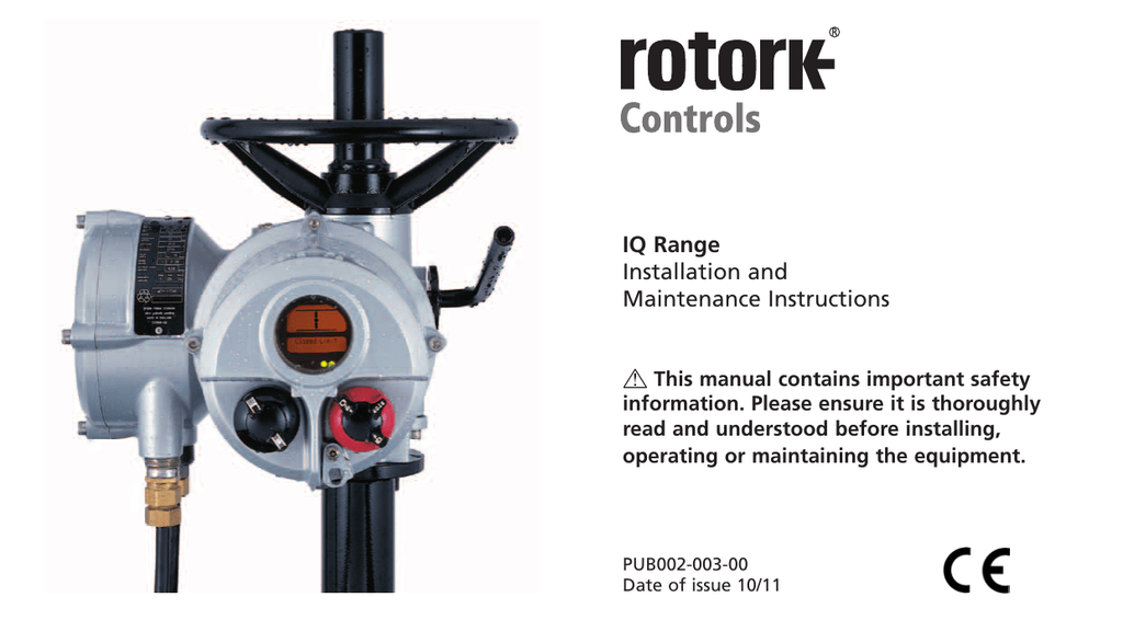
For specials or if you cant find what you want please contact rotork. Iq mk3 part turn iqt folomatic cpt current position transmitter.

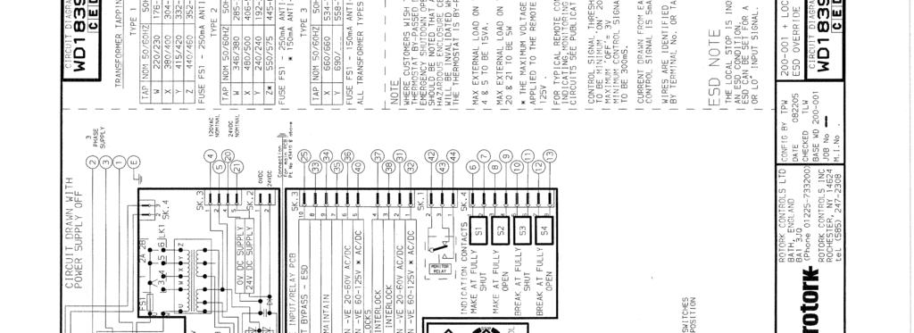
Wiring Diagram Rotork Diagram Base Website Diagram Rotork
Rotork iqt wiring diagram. Rotork wiring diagram selector. Iq3iqt3 range rotork wiring diagram selector. 3 5 6 7 4 8. For further information please refer to our privacy policyprivacy policy. The wiring diagram selector returns standard iq3iqt3 range wiring diagrams only. Iqt 125 250 500 size 1 iqt 1000 2000 size 2 iqt 1000 2000 fail safe option size 2 case studies.
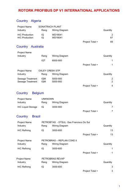
Valve actuation at the worlds largest flow metering calibration facility. Rotork actuator wiring diagram wiring diagram is a simplified agreeable pictorial representation of an electrical circuit. The rotork iqt range the first 14 turn valve actuator that you can commission and interrogate without removing electrical covers. The wiring diagram selector returns standard iqt2 pro legacy wiring diagrams only. Rotork actuators with profibus. By using this site you agree to the usage of cookies.
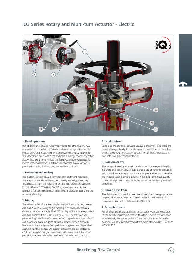
Iee wiring regulations should be applied. Iq mk3 part turn actuator iqt125 iqt250 iqt500 dimensional drawing. Rotork valve automation at solar power plants. Also the user should be fully aware of his duties under the health and safety act 1974. 0 iq 3 phase or iqt 3 phase 1 phase dc with 24vdc customer supply 1 iq 3 phase or iqt 3 phase 1 phase dc with 120vac customer supply 2 iq 1 phase with 24 vdc customer supply 3 iq 1 phase with 120 vac. Iq mk3 part turn iqt basic diagram.
It shows the components of the circuit as simplified shapes and the capability and signal connections between the devices. For specials or if you cant find what you want please contact rotork. Close we use cookies in order to optimise this website and for continuous improvement. Valve actuation and control in the modern refinery. Please select a language andor file type from the list below.

