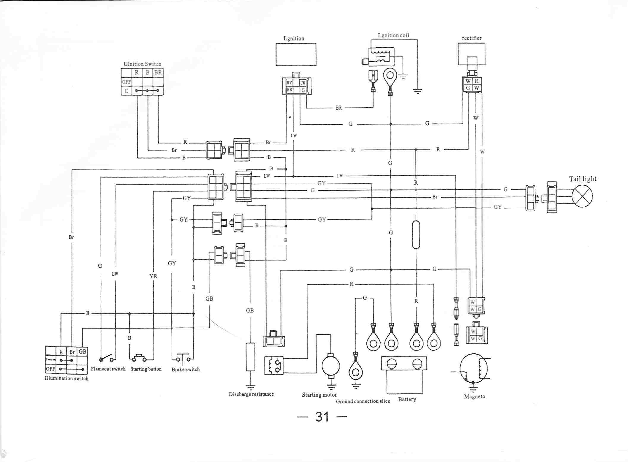
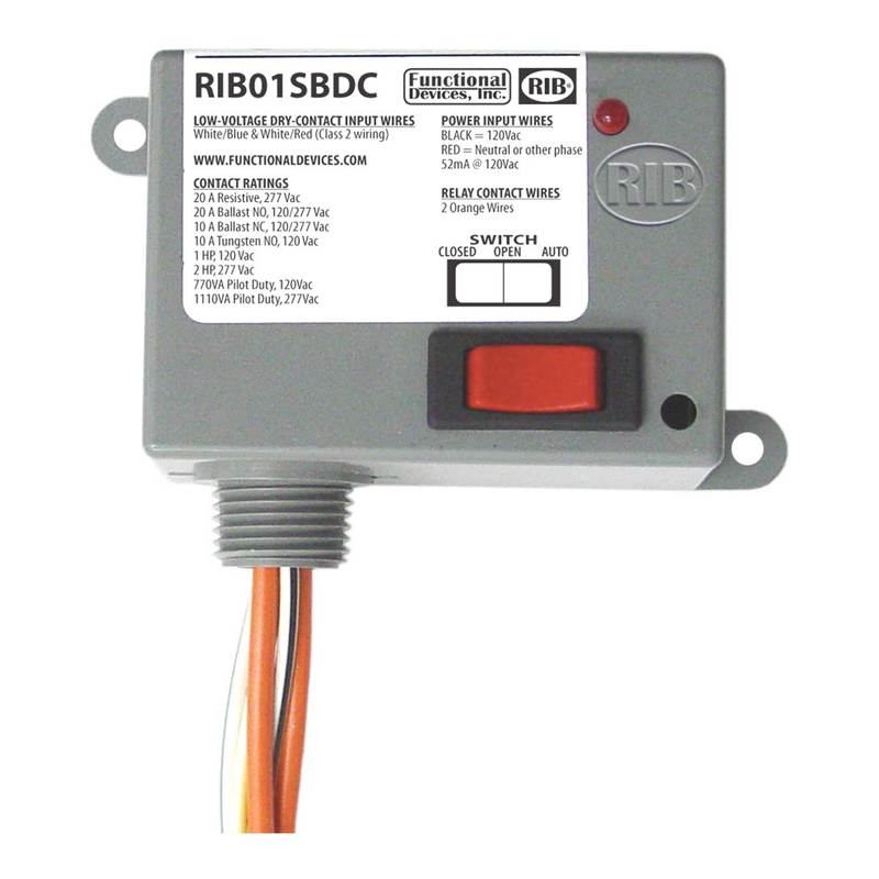
In this setup you can see the device mounted on the enclosure. Close whitered wire to whiteblue wire to activate relay.
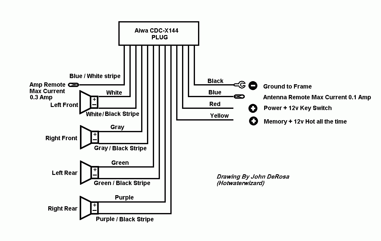
Diagram Based Aiwa Cdc Wiring Diagram Completed Diagram
Rib21cdc wiring diagram. The dry contact input rib series is controlled by class 2 circuits with a dry contact from a bas controller thermostat switch another relay or a solid state switch. It shows the elements of the circuit as streamlined forms as well as the power and also signal links between the devices. The relay contacts are isolated from the input power and the dry contact input. Close whitered wire to whiteblue wire to activate relay. If more than one dry contact rib shares a single dry contact input whiteblue must be common. Functional devices is the established leader in the hvac building controls and energy management industries for american designed and manufactured building automation and control devices.
Variety of ribu1c wiring diagram. Welcome to the relay in a box product series. If more than one dry contact rib shares a single dry contact input whiteblue must be common. It shows how the electrical wires are interconnected and can also show where fixtures and components might be attached to the system. A wiring diagram is a streamlined standard photographic depiction of an electric circuit. The power to energize the rib series comes from the load being controlled or a local power source near the relay.
Rib21cdc enclosed relay 10 amp spdt class 2 dry contact input 120 277 vac power input rib21cdc rd red housing rib21cdc n4 nema 4x housing ul508 only specifications dry contact relays. Today we will be looking at the rib21cdc which is a dry contact input relay. Rib21cdc enclosed relay 10 amp spdt class 2 dry contact input 120 277 vac power input rib21cdc rd red housing rib21cdc n4 nema 4x housing ul508 only made in usa meets buy. If more than one dry contact rib shares a single dry contact input whiteblue must be common. Ribu1c wiring diagram what is a wiring diagram. Rib21cdc enclosed relay 10 amp spdt class 2 dry contact input 120 277 vac power input rib21cdc rd red housing rib21cdc n4 nema 4x housing ul508 only specifications dry contact.
Wiring installation power input relay contact rib located at rtu or load bas controller thermostat or other dry contact switch minimum rating 7 vdc 1µa low voltage class 2 wiring starter power 208 480 vac rtu or other load rib01sbdc rib21cdc. A wiring diagram is a straightforward visual representation with the physical connections and physical layout of your electrical system or circuit. Close whitered wire to whiteblue wire to activate relay. Functional devices rib21cdc enclosed pilot relay 10 amp spdt 12 hp 120 277 vac power input enclosed pilot relay 10 amp spdt 12 hp 120 277 vac power input.
