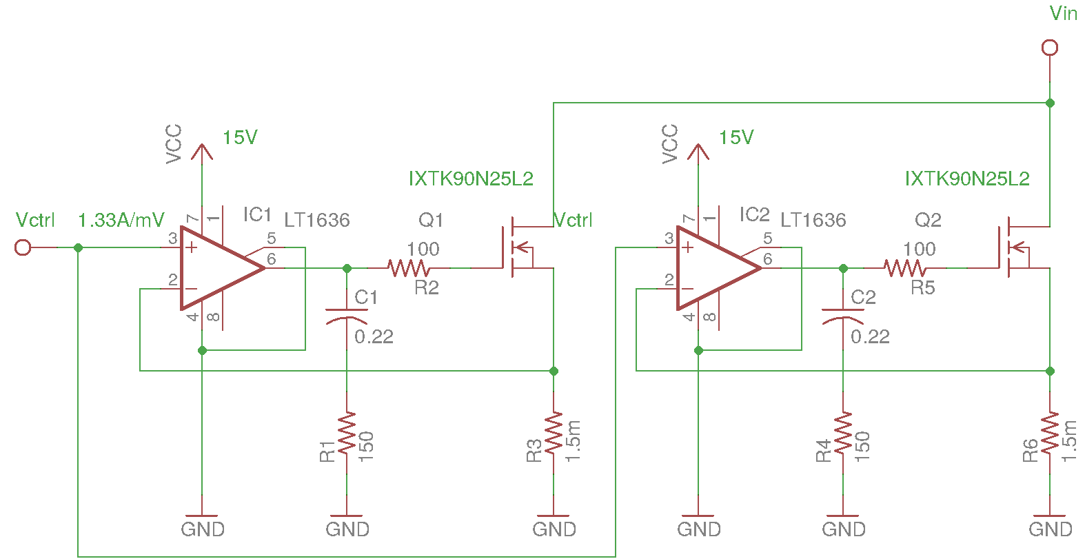
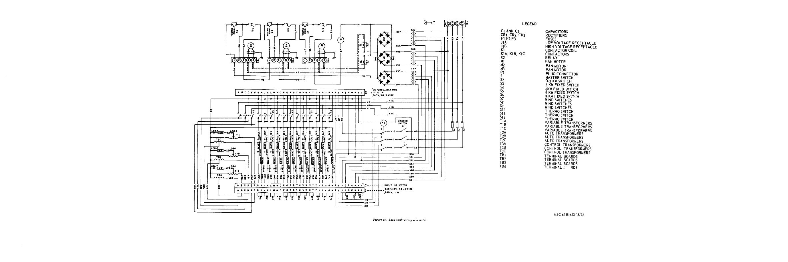
Shock hazard load banks contain lethal voltages when connected to the power source. It shows the components of the circuit as simplified forms and the power and signal links in between the gadgets.

10 Rotor Circuit Diagram Including A Resistive Load Bank
Resistive load bank wiring diagram. This load bank is used in the generator and ups industries. Simplex load banks technical data and tools section. A wiring diagram is a streamlined traditional photographic representation of an electric circuit. Collection of avtron load bank wiring diagram. It shows the elements of the circuit as simplified forms as well as the power as well as signal connections in between the devices. A wiring diagram is a streamlined standard photographic depiction of an electric circuit.
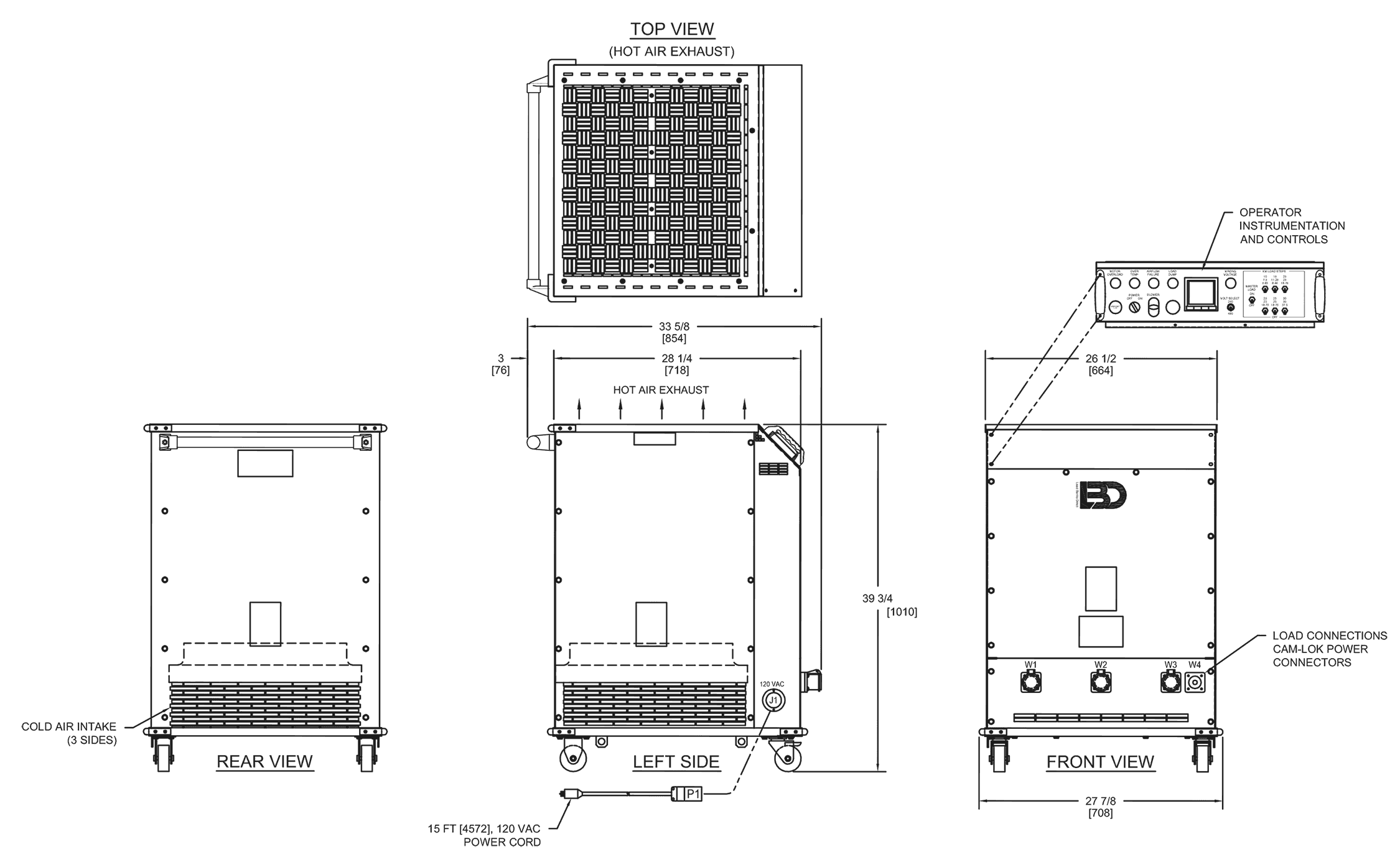
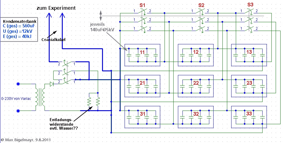
The asco 4100 load bank is designed for permanent outdoor installation when 50 to 150 kw loading is required. A load bank is a device which develops an electrical load applies the load to an electrical power source and converts or dissipates the resultant power output of the source. Power to the load resistors main input load bus power to fan motor circuits and power to 120 vac control circuits must be removed before servicing. Read more about load bank fundamentals at simplex. Capacitor bank as load. The 4100 is designed for dedicated on site testing.
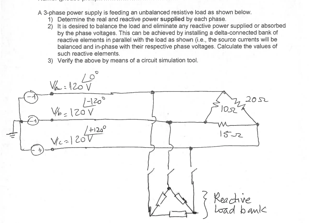
A load bank with inductive elements could be added for a short period so that commissioning and acceptance tests can be carried out. I am looking for an ac load bank to complete my power supply. Any suggestions from where power electronics. Load bank university project homework help. Load bank main input load bus blower motor circuit and 120 vac control circuits. See our drawing library.
For additional information please contact the simplex service department. Keep in mind that the ac load banks in this catalog are generally 3 phase 3 wire loads meaning that a neutral is not required and that loads are applied in 3 phase balanced steps. See all load banks. Simplex load banks and fuel supply systems for the standby power generation industry. Power bank with low discharge load. Looking for transfer switch drawings.
Medium voltage load banks. Resistive reactive load banks. Current current expressed in amperes is found by the following formula. Collection of avtron load bank wiring diagram. A load bank is intended to accurately mimic the operational or real load which a power source will see in actual application. One example of the use of multiple load banks might be where a purely resistive load bank is to be permanently installed for ongoing routine maintenance engine tests.
Analog mixed signal design.


