Veja aqui remedios naturais terapias alternativas sobre pcc 1302 wiring diagram. Bosch charging alternator wiring diagram.

Pcc1302 Operator Instructions Menu Computing
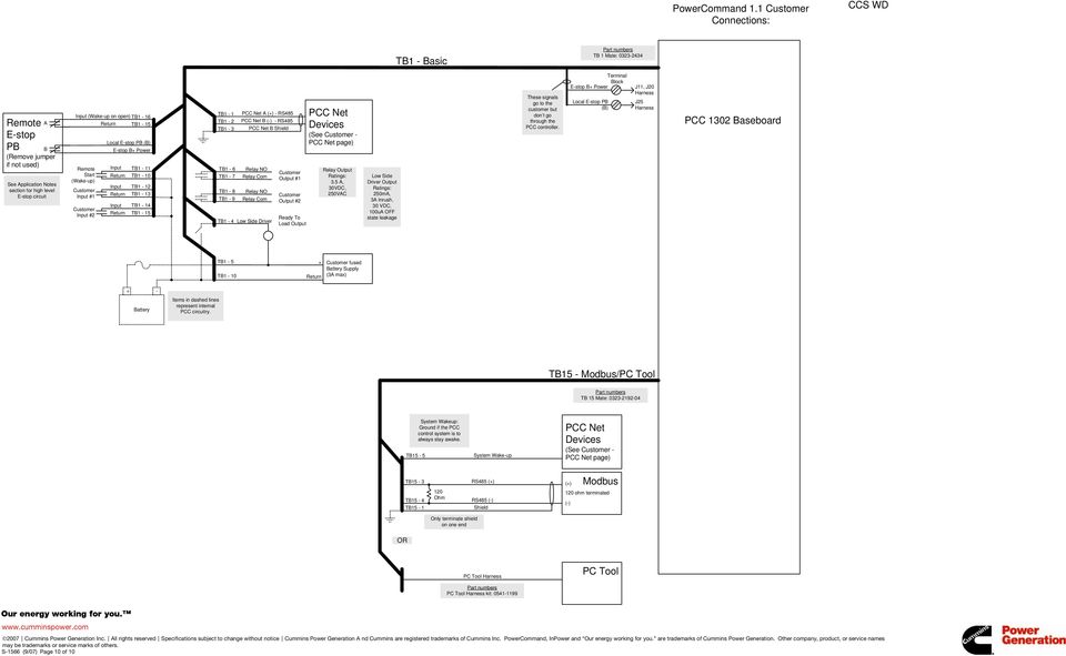
Pcc 1302 wiring diagram. Engine the 1302 can communicate with and control the generator set. Power command digital generator set control pcc1302 cummins onan harness control 327 1617 01 0338 4978. Bosch type charging alternator. Pcc 2100 commissioning guide linesrev26. It requires battery voltage input from the genset starter batteries. Operator and installation manual remote network monitoring powercommand iwatch 100 english 12 2007 9000545 issue 3.
The voltage regulation system is full wave rectified and has an scr output for good motor starting capability. Description 1 tb15 2 tb1 figure 4. Cummins pcc 1302 wiring diagram. The control system provides a field adjustable trim to select either 12v24v battery operations for. D approx 5 ohm input impedance run b. The hmi 211 can be powered from pcc 1302 if within 500 feet 152 meters.
Connecting the hmi 211 remote no. Descubra as melhores solu es para a sua patologia com todos os beneficios da natureza outros remédios relacionados. Pcc 1302 terminal blocks tb1 and tb15 6. The powercommand control is compatible with shunt or pmg excitation style. Manual operación pcc 1302. If greater than 500 feet power must come from an.
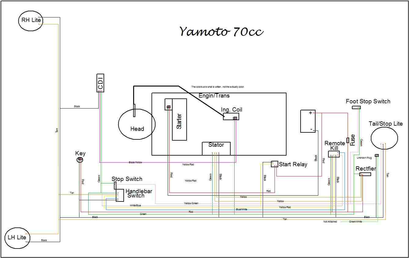
1224v battery the 1302 series control provides 12 and 24 vdc battery operation capability for genset system. Denso charging alternator wiring diagram. It is suitable for use with reconnectable or non reconnectable generators and. Diagrama pcc 3300revm wiring diagrams. Service manual pcc 3201. Wiring instruction for 70cc 110cc and 125cc with yellow plug.
A fast acting ul certified ceramic fuse with a rating. 6303270 for com plete illustration. Microsoft word ps0500 training module65pdf. Pcc 1302 description the powercommand generator set control is suitable for use on a wide range of generator sets in non paralleling applications. Pcc 1302 wiring diagram pdf. Alternator control the 1302 includes an integrated line to line sensing voltage regulation system that is compatible with shunt or pmg excitation systems.
Referring to wiring diagram. Manual de partes ps 500pdf. Battery charging alternator input alternator connections. 1 j1 and j2 wiring connectors 2 p1 harness plug figure 3. See the wiring schematic in figure 5.


