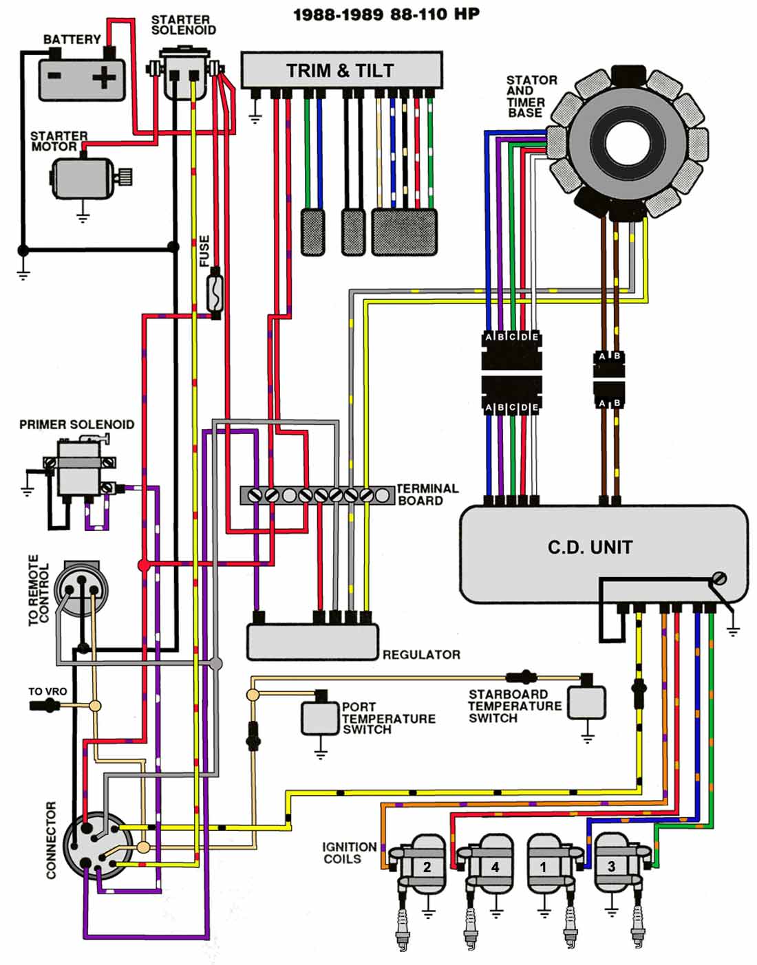
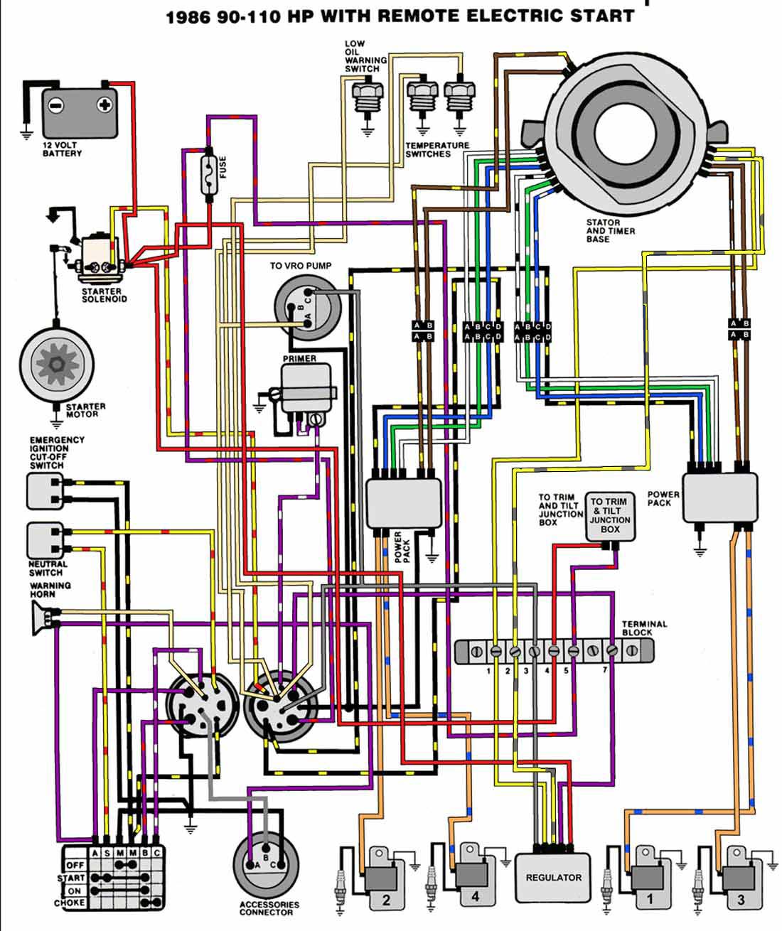
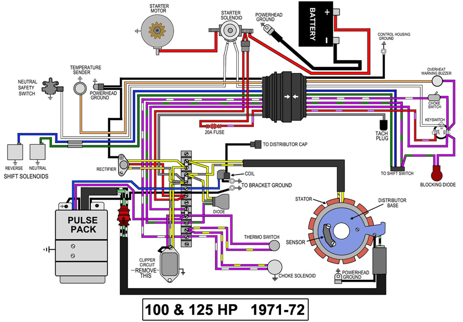
Outboard wiring diagrams these diagrams are accurate to the best of our knowledge. Un fused wire from battery.
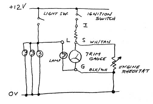
Omc Trim Gauge Wiring Diagram Wiring Diagram
Omc trim gauge wiring diagram. Tan with or without stripes. Shorting or stop circuit. Collection of evinrude wiring diagram outboards. All you have to do is hook up the three wires that are under your console in the keyswitch wiring harness black wire to ground terminal on the trim gauge purple to the power or i terminal and white tan to the sender terminal. However variations can exist such as between remote control and tiller models. Omc cobra volvo penta sx engine new trim gauge install duration.
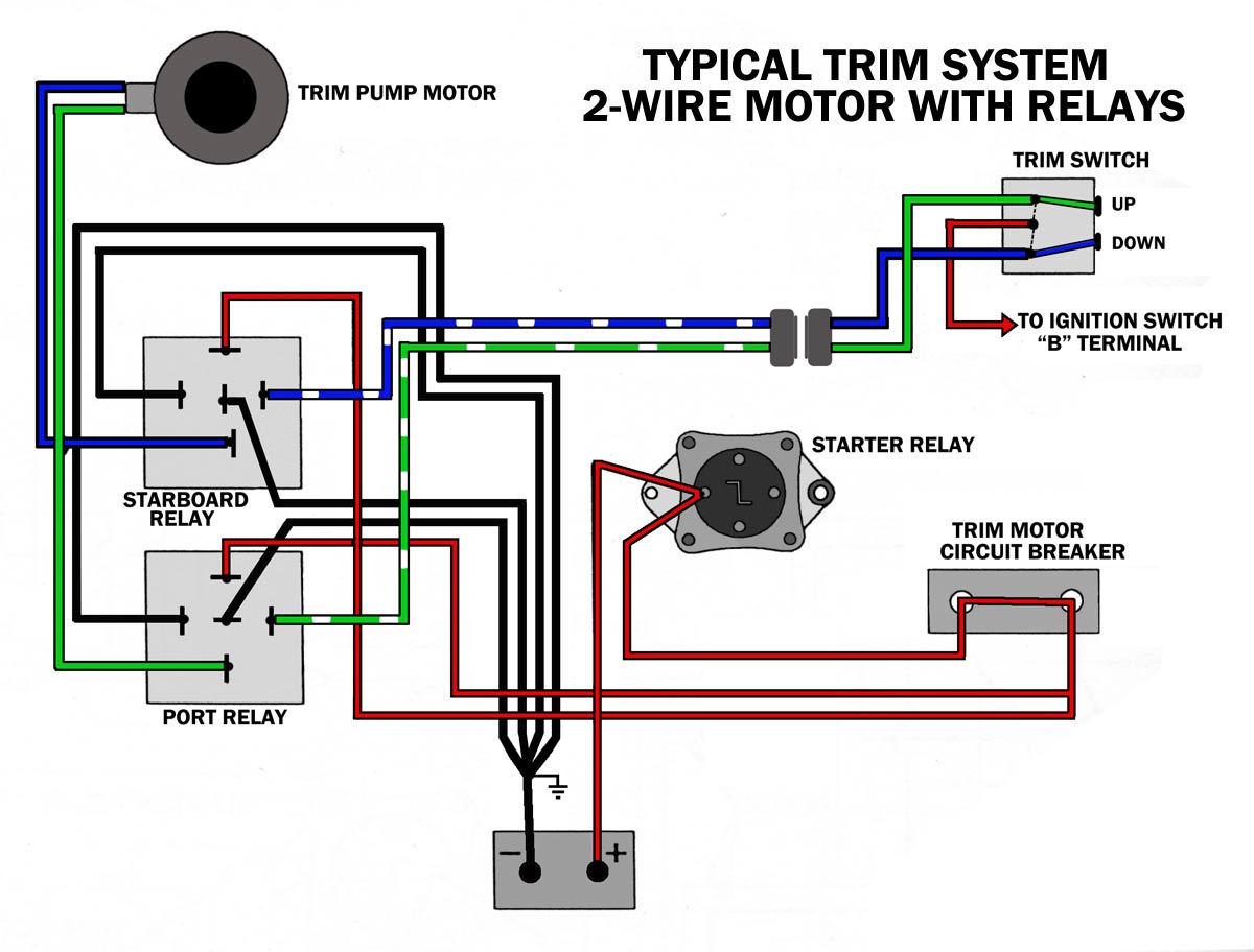
Outboard trim tilt relays explained. V 4 120 140 hp 1988 89. Colors listed here may vary with year model but in general should be a good guide when tracing yamaha wiring troubles. Un fused wire from battery. The best part is you do not need a wiring diagram. Wiring a newer outboard controller to a older engine duration.
White with light brown stripe. Trim trailer switch. Fuel sender to gauge. Omc cobra volvo penta sx engine new trim gauge install duration. Trim down switch. V 4 models early.
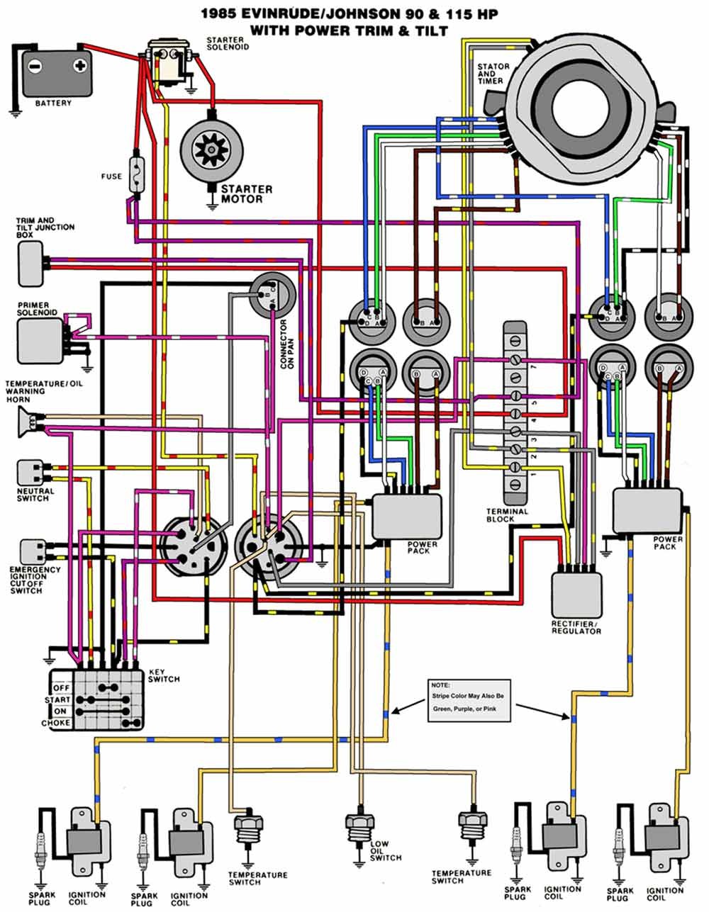
Here is a listing of common color codes for yamaha outboard motors. Super easy boat wiring and electrical diagrams step by step. Temperature switch to warning horn andor temperature sender to temperature. V 4 90 115 hp 1985. A wiring diagram is a simplified standard photographic representation of an electrical circuit. Trim sender to trim gauge.
Purple white stripe. Black yellow stripe. There is an industry standard set of wire codes in general use by most manufacturers except yamaha. Trim down switch. Protected fused wire from battery andor protected 12 volt to. Super easy boat wiring and electrical diagrams.
Red purple stripe. Shorting or stop circuit. Yamaha trim gauge wiring diagram wiring diagram is a simplified within acceptable limits pictorial representation of an electrical circuitit shows the components of the circuit as simplified shapes and the knack and signal friends amid the devices. Trim sender to trim gauge. V 4 motors 1982 1984 power trim. It shows the parts of the circuit as streamlined shapes as well as the power and signal links in between the tools.
Black with yellow stripe. V 4 88 110 hp 1988 89. Ignition switch to 12 volt positive. V 4 90 115 hp 1986.
