Rl44 spst relay. Use accessory relays when installing auxiliary lighting adding horn circuits or any other electronics to your vehicle.

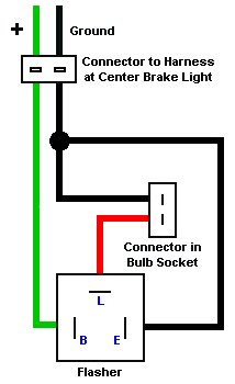
Heavy Duty Flasher 42011 2 Pin Electronic 12v
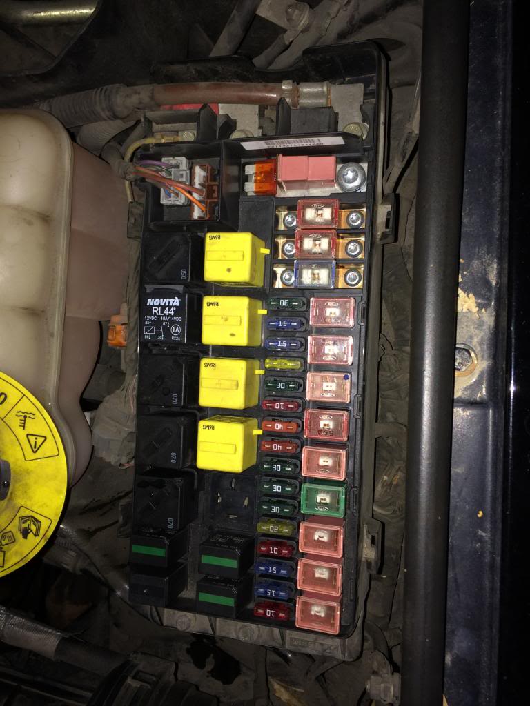
Novita relay wiring diagram. All right could you post your novita rl44 relay wiring diagram especially where thesave on novita relay socket rs40 at advance auto parts. Rl44 spst relay rl45 spdt relay. Assortment of 12 volt relay wiring diagram. Novita lm470 wiring diagram 08122018 08122018 5 comments on novita lm470 wiring diagram diode dynamics lm led flasher module to slow down the blinking to regular speed you can add resistors to increase the circuits power consumption again. Electrical wiring diagram house circuit home rh chicagoredstreak. Click here to simplify the installation of your rl44 accessory relay and cleanup your wiring with the rs40 relay installation socket.
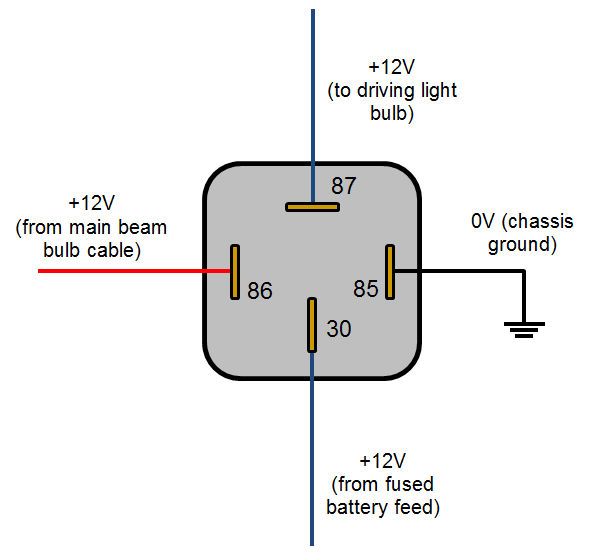
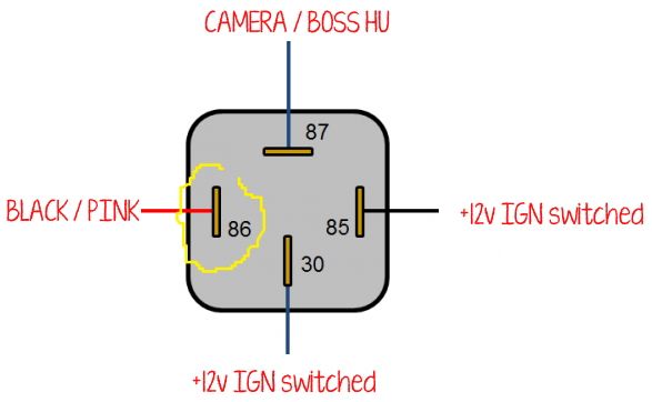
Rl novita accessory relays can be installed in a variety of vehicles and are designed to reduce good 4 pin wire for fogdriving lights. It reveals the components of the circuit as simplified shapes and also the power and signal connections in between the tools. The square relay pinout shows how the relay socket is configured for wiring. Instructions for wiring a standard automotive relay with descriptions of the pin out and the schematic. Buy online pick up in store in 30 minutes. The relay allows full power to the component without needing a switch that can carry the amps.
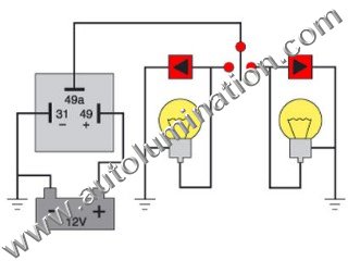
The switch only controls the relay. B x 49 battery power input c2 hazard switch ground e 31 ground h hazard switch i ignition l 49a load p pilot lamp s sense. A wiring diagram is a simplified traditional pictorial depiction of an electrical circuit. Dozens of the most popular 12v relay wiring diagrams created for our site and members all in one place. Dont have a wiring diagram to know if that exists. I go over what each contact of the relay is for and how to understand the schematic that is.
The relay then provides a direct connection to the battery. It should be noted that either the power86 or ground85. A relay is typically used to control a component that draws high amperage. If you need a relay diagram that is not included in the 76 relay wiring diagrams shown below please search our forums or post a request for a new relay diagram in our relay forum. This pinout image is only a 2 pole diagram for room on the page purposes but you can get the picture here with this one since a 3 pole will just have 1 more set of contacts. To confirm the wiring configuration consult a wiring diagram from google images or a service manual.

