The smoke detectors wiring harness has two parts. The fixed wires and the wires that protrude from the harness.

Notifier System 500 Installation Operation And Programming
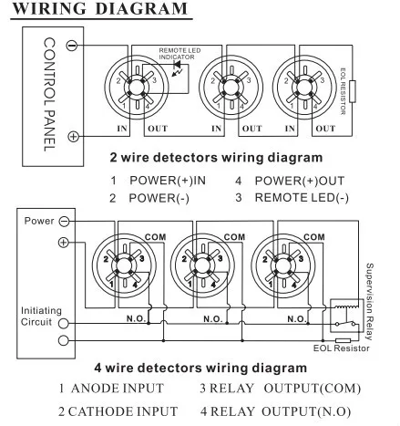
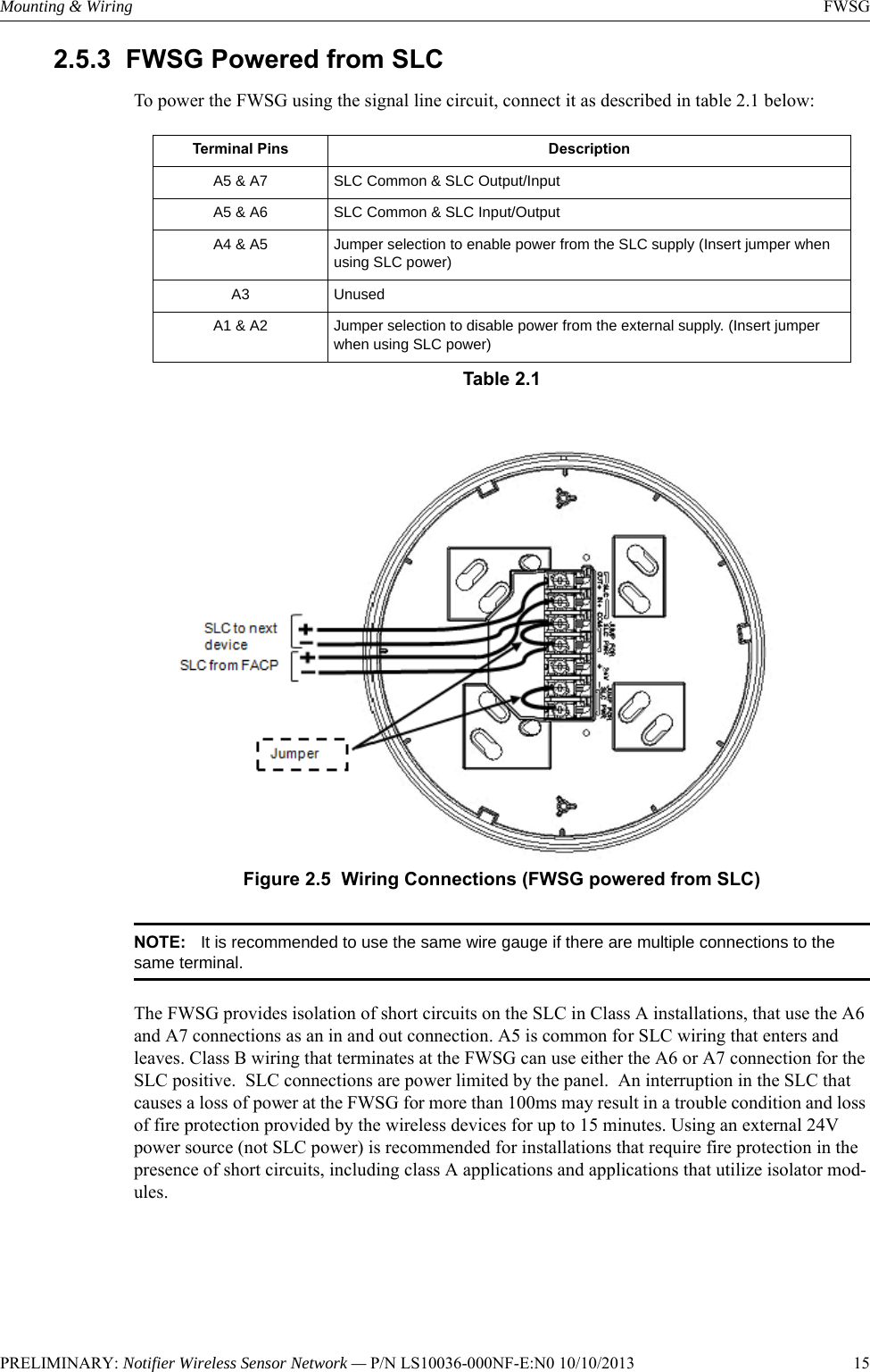
Notifier smoke detector wiring diagram. White black and yellow. Use the slot in the retaining clip to hold the spring against the terminal as shown in figure 1. Notifier by honeywell is the largest manufacturer of engineered fire alarm systems with over 400 distributors worldwide and regional support operations on every continent. Wiring diagram for a typical 2 wire detector system. As a result existing nonaddressable loops can be integrated into a notifier addressable system the module monitors a zone of two wire non addressable smoke detectors. You should be able to see three wires coming out of the harness.
Fsp 851 and fsp 851t are listed for use in ducts. For pendent mount applications where remote testing is not needed the 2151 needs to be used with either the b114lp or b114lpbt base. Wiring diagram for 2 wire duct smoke detector to rts451rts451key remotetest station in out 1st detector in loop d2 riw3v optional remote alarm led 44 vdc nom. Wiring smoke detectors electrical project skill level. The notifier sd 651 plug in smoke detectors offer superb performance and reliability in a profile which is just 2 51 cm deep. In alarm e o l r style d optional wiring notifier control panel alarm initiation loop.
After the detector base is wired and attached to the electrical box position the shorting spring against terminal 3. Or the system smoke detector application guide available from notifier. See duct applications guide a05 1004 for details on pendant mount applications. Photoelectronic low profile plug in detector for special applications note. Basic electricians pouch of hand tools non metal step ladder and a voltage tester. These products are not listed for use inside duct smoke detectors.
Know the basics of smoke detector wiring and learn how these detectors are connected together in a series. Model sd 651 photoelectric sensor can be used with a variety of different adapter bases in several wiring configurations and voltages. For signal wiring the wiring between interconnected detectors it is recommended that the wire be no smaller than awg 18. In alarm in out last detector in loop d2 riw3v optional remote alarm led 44 vdc nom. Each mczr uses one of 99 available module addresses on a loopnotifier cmx 2 addressable control module rybb fire alarm parts service repairspreview notifier mmx 1a. However the screws and clamping plate in the base can accommodate wire sizes up to awg 12.
Upc code model cross reference. The use of twisted pair wiring for the power and loop is recommended to minimize the effects of electrical interference.
