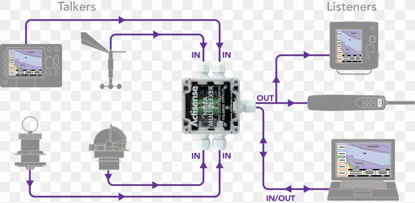
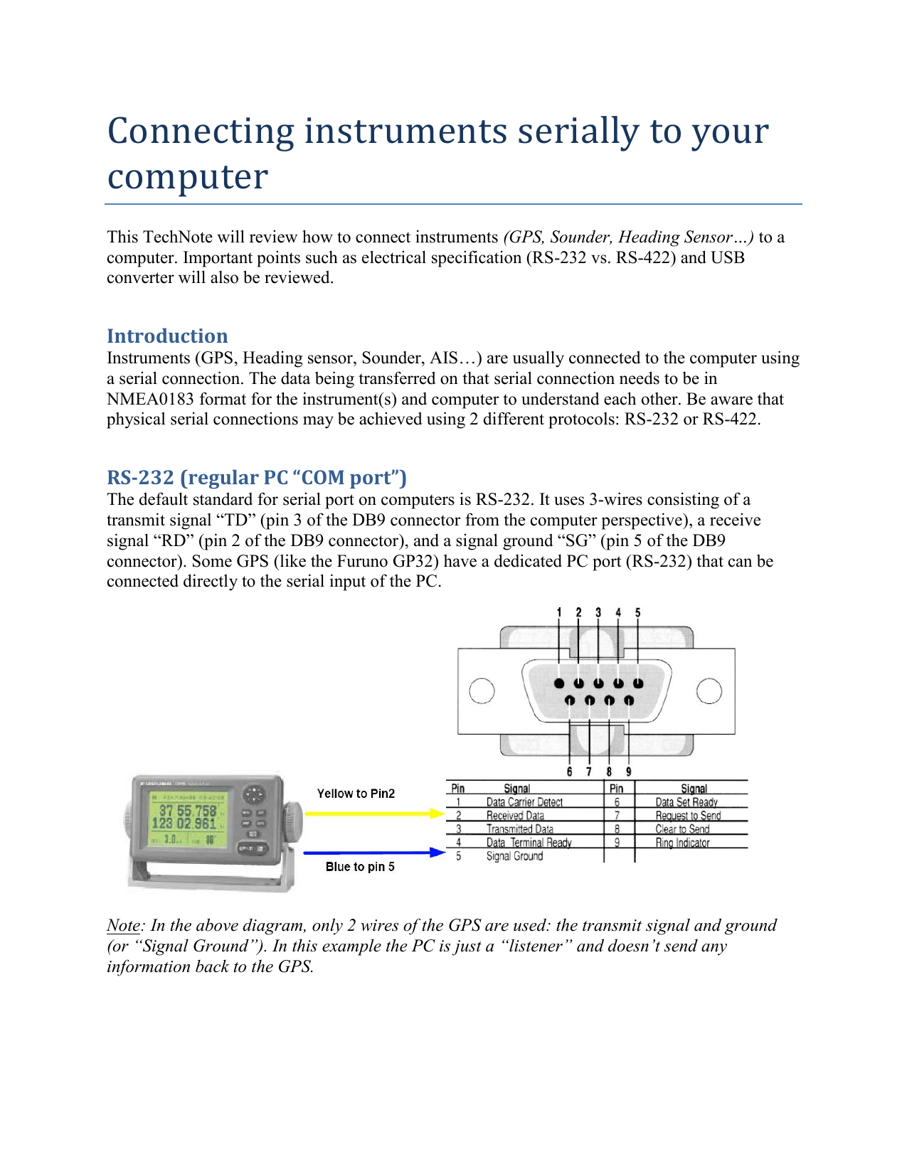
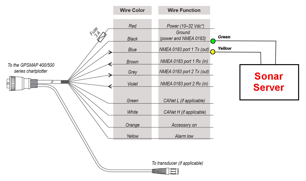
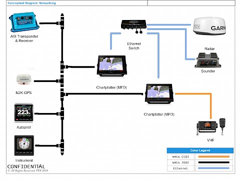
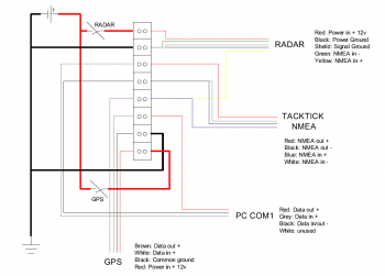
It shows the components of the circuit as simplified shapes and the capability and signal contacts along with the devices. A wiring diagram is a simplified conventional pictorial depiction of an electrical circuit.

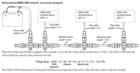
Lowrance Nmea 2000 Network Basics
Nmea wiring diagram. Nmea 0183 connection diagram. A wiring diagram is a simplified conventional photographic depiction of an electric circuit. Nmea 2000 wiring diagram wiring diagram is a simplified usual pictorial representation of an electrical circuit. Older gamin units older garmin units like the 3000 series or 498 use the black power wire ground as the nmea 0183 transmit and receive negative. Installing and connecting devices using the nmea 0183 interface standard. It reveals the parts of the circuit as simplified forms as well as the power and signal connections in between the devicespower connections for lowrance nmea network.
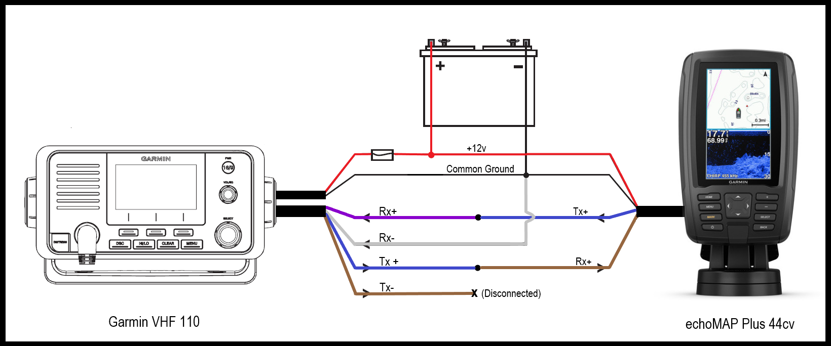
Collection of nmea 2000 wiring diagram. Every so often we will see other units that do this if you unit does this just connect the tx and rx wires from the unit you are interfacing to the sam. Assortment of nmea wiring diagram. Item description 12 vdc power source wiring harness nmea 0183 compliant device item garmin wire function garmin wire color nmea 0183 device wire function power red power ground black data ground tx blue. Prior to nmea 0183 version 20 including nmea 0180 and nmea 0182 the hardware employed a single ended interface implemented with one signal wire and a common ground based on eia 232. It reveals the parts of the circuit as streamlined forms and also the power and signal links between the gadgets.
There are multiple versions of the nmea 0183 specification in use in the marine industry. This confuses the heck out of people.
