The control unit and asso. 2 nfs2 640e installation manual pn 52741k1 03062012 fire alarm system limitations while a fire alarm system may lower insurance rates it is not a substitute for fire insurance.
Wfsmm Wireless Monitor Module User Manual Slc Gateway
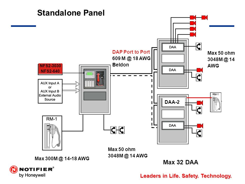
Nfs 640 wiring diagram. Nfs2 640e operations manual pn 52743f1 06162011 3 installation precautions adherence to the following will aid in problem free installation with long term reliability. Disconnect all sources of power before servicing. Control unit and associ. The control unit and asso. Nfs2 640e installation manual pn 52741p2 71014 3 installation precautions adherence to the following will aid in problem free installation with long term reliability. Warning several different sources of power can be connected to the fire alarm control panel.
Field wiring an auxiliary relay module. Connect all available external wiring at this time. Nfs 640 installation manual pn 51332b1 12012003. Warning several different sources of power can be connected to the fire alarm control panel. An automatic fire alarm systemtypically made up of smoke detectors heat detectors manual pull stations audible. Warning several different sources of power can be connected to the fire alarm control panel.
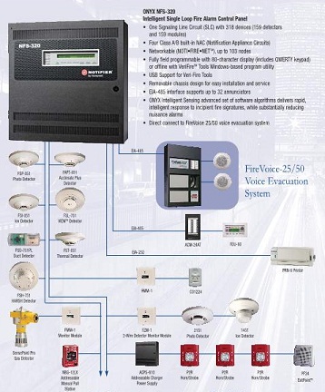
The nfs2 640 is engineered for mid size applications designed to maximize flexibility and customization that meet your specific life safety needs. Warning several different sources of power can be connected to the fire alarm control panel. Nfs 640 installation manual pn 51332b2 07272004 3 installation precautions adherence to the following will aid in problem free installation with long term reliability. The other end of the cable is connected to jumper jp5 on the crm 4rk or cre 4. Disconnect all sources of power before servicing. Disconnect all sources of power before servicing.
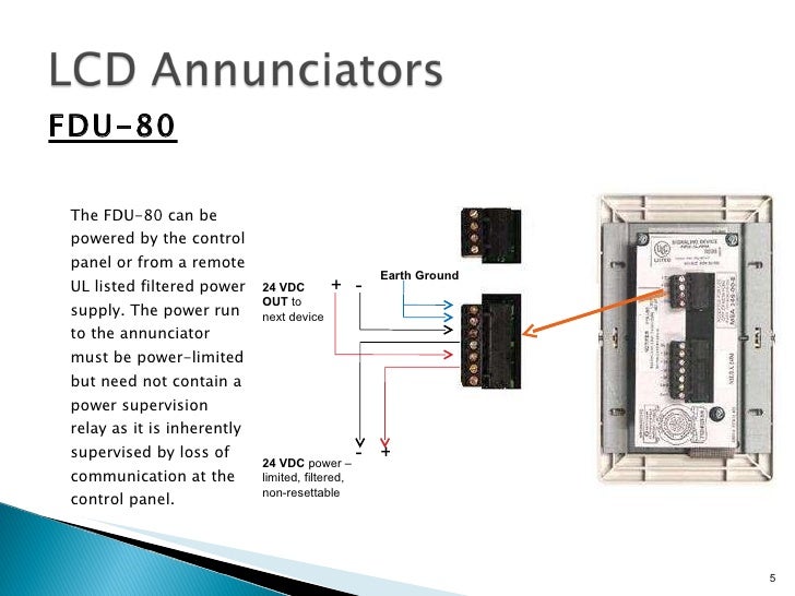
Nfs 640 operations manual pn 51334b 10032003 3 installation precautions adherence to the following will aid in problem free installation with long term reliability. Nfs 640 installation manual pn 51332b1 12012003 3 installation precautions adherence to the following will aid in problem free installation with long term reliability. Warning several different sources of power can be connected to the fire alarm control panel. Notifier nfs2 3030 wiring diagram wiring diagram is a simplified gratifying pictorial representation of an electrical circuitit shows the components of the circuit as simplified shapes and the power and signal contacts amongst the devices. Disconnect all sources of power before servicing. The control unit and asso.
The nfs2 640 intelligent fire alarm control panel is part of notifiers ul listed onyx series. Refer to section 383 field wiring an auxiliary relay module. Home fire alarms security systems bass united. Control unit and associ. Disconnect all sources of power before servicing.
