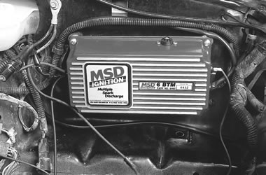
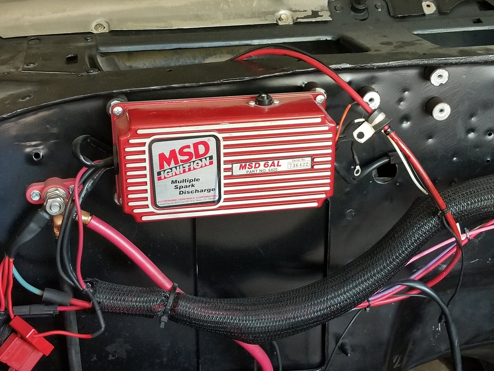
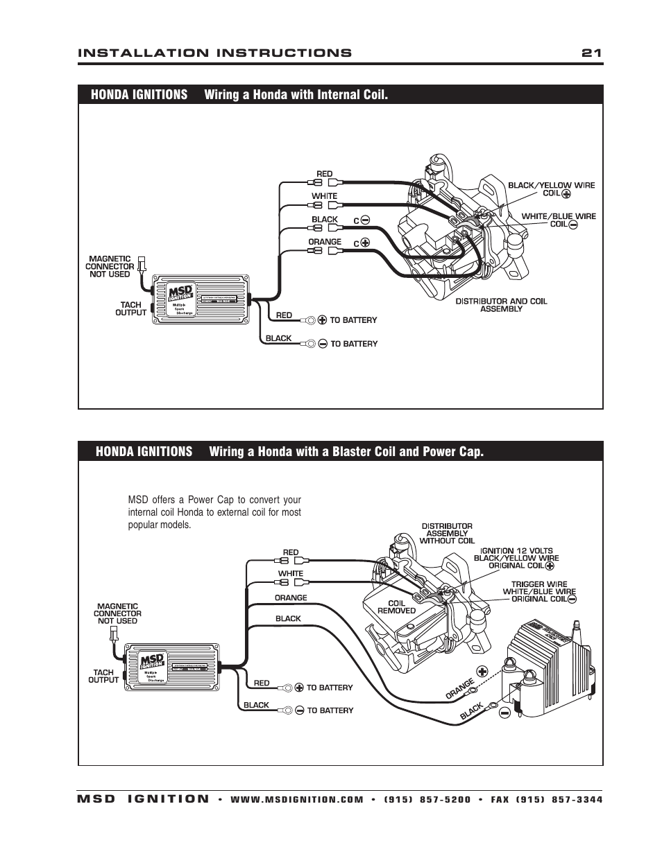
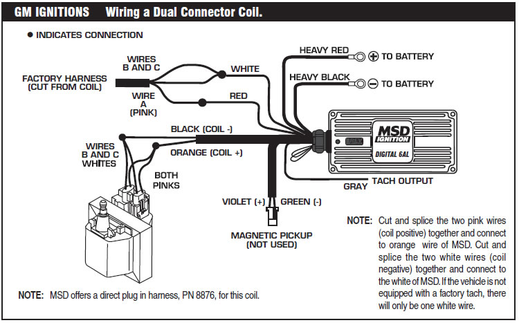
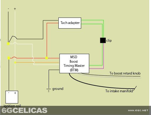
Msd 6btm wiring diagram wiring diagram is a simplified tolerable pictorial representation of an electrical circuit. The 6 btm is ideal for engines with a turbo or supercharger.

Msd 6462 6 Btm Ignition Control Box
Msd btm wiring diagram. Assortment of msd 6btm wiring diagram. Solid core spark plug wires cannot be used with an msd ignition. The purpose is the very same. Literally a circuit is the path that enables electrical energy to flow. A helically or spiral wound wire must be used. This style wire provides a good path for the spark to.
Wound wire and proper routing are required to get the best performance from your ignition such as the msd heli core or 85mm super conductor wire. A length of 18 tubing is required. It shows the components of the circuit as simplified shapes and the aptitude and signal connections along with the devices. The result is a great increase in power but this can. A wiring diagram is a simplified conventional pictorial depiction of an electric circuit. Not only will the engine benefit from msds full power cd sparks but there is also an adjustable boosttiming retard circuit to prevent detonationwhen your turbo or blower forces the airfuel mixture into the engine the cylinder pressure inside the combustion chamber increases.
Msd 6btm wiring diagram a novice s guide to circuit diagrams a very first take a look at a circuit layout might be complex however if you can check out a train map you can check out schematics. 1 msd 6 series ignition 1 100v1a diode 1 harness pn 8860 4 wire splicers 1 harness pn 8861 2 wire ties 1 18 ground wire 1 faston receptacle 1 white jumper 2 faston straight terminals 1 red jumper 2 violet jumpers. Msd 6btm pn 6462 additional parts supplied. It reveals the parts of the circuit as simplified shapes as well as the power as well as signal connections between the tools. This is an addendum to the supplied instructions that detail the function and wiring of. Msd 6 series installation instructions 6a 6al 6t 6btm 6tn 6aln parts included.
1 2 pin weathertight connector 1 control dial 1 38 rubber bushing 4 self tapping screws addendum figure 1 connecting the boost lines and connector. Getting from factor a to aim b.
