Basic wiring for motor control technical data. Check them out today.

How To Add Redvision To An Existing Bms Setup Redarc
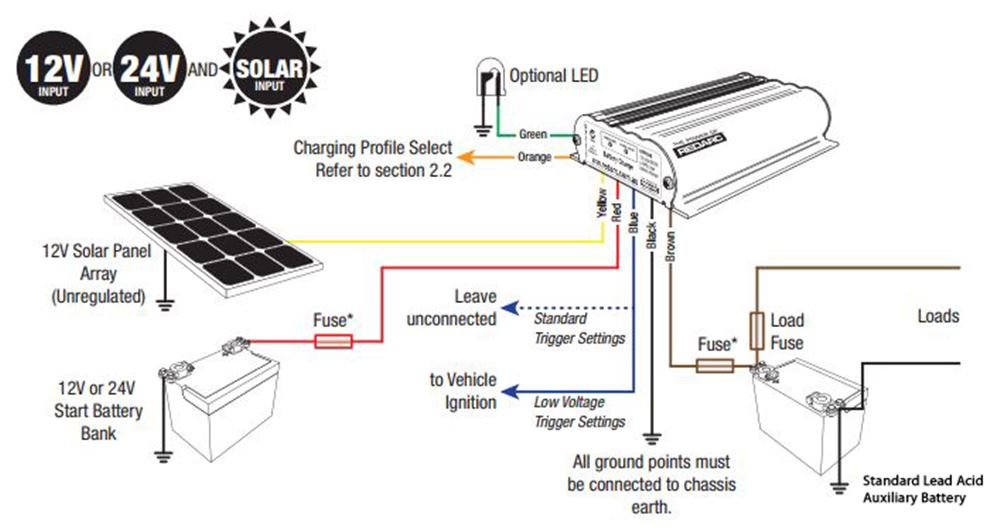
Manager 30 wiring diagram. Usually the wiring diagram refers to the electrical schematic or circuits diagram. Redarc electronics have a large database of faqs tech tips wiring diagrams and how to guides. The manager30 is a complete battery management system for charging auxiliary batteries used in recreational automotive and marine applications. Wiring diagram software with built in stencils for fast and efficient electrical wiring diagram design. Solar panels to unit to battery and do i need to put a fuse or circuit breaker somewhere what size if i do any help would be great thanks i have 1 300w solar panel and two 12v batteries. Wiring diagrams sometimes called main or construction diagrams show the actual connection points for the wires to the components and terminals of the controller.
The dual battery system incorporates ac dc and solar inputs to achieve the best charge for an auxiliary battery. L9 20r l9 30r 600v ac equip. Only one of the prongs supplies power and it provides the expected 120 volts at 30 amps. Using the calculation of amps30 x volts120 watts this calculates the total provided power to a rough 3600 watts of electricity. Wiring diagrams show the connections to the controller. 3 pole 3 wire 125v250v ac 3ø 250v ac 3ø 480v ac l8 20r l8 30r 480v ac g equip.
10030 wiring diagram i brought the 10030 mppt charge controller wanting a full wiring diagram picture how to wire it up as im not sure. Its three prong receptacle visually defines this socket type. Easy to create wiring plans schematics circuit diagrams and more. The new redarc manager30 s3 is a 30a state of the art battery management system designed to charge and maintain auxiliary batteries by incorporating ac dc and solar inputs ideal for recreational vehicles caravans and camper trailers with multiple battery banks. Wiring diagram book a1 15 b1 b2 16 18 b3 a2 b1 b3 15 supply voltage 16 18 l m h 2 levels b2 l1 f u 1 460 v f u 2 l2 l3 gnd h1 h3 h2 h4 f u 3 x1a f u 4 f u 5 x2a r. 3ø wiring diagrams 1ø wiring diagrams diagram er9 m 3 1 5 9 3 7 11 low speed high speed u1 v1 w1 w2 u2 v2 tk tk thermal overloads two speed stardelta motor switch m 3 0 10v 20v 415v ac 4 20ma outp uts diagram ic2 m 1 240v ac 0 10v outp ut diagram ic3 m 1 0 10v 4 20ma 240v ac outp uts these diagrams are current at the time of publication.

