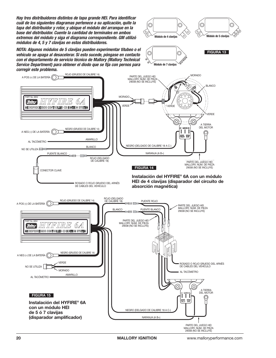
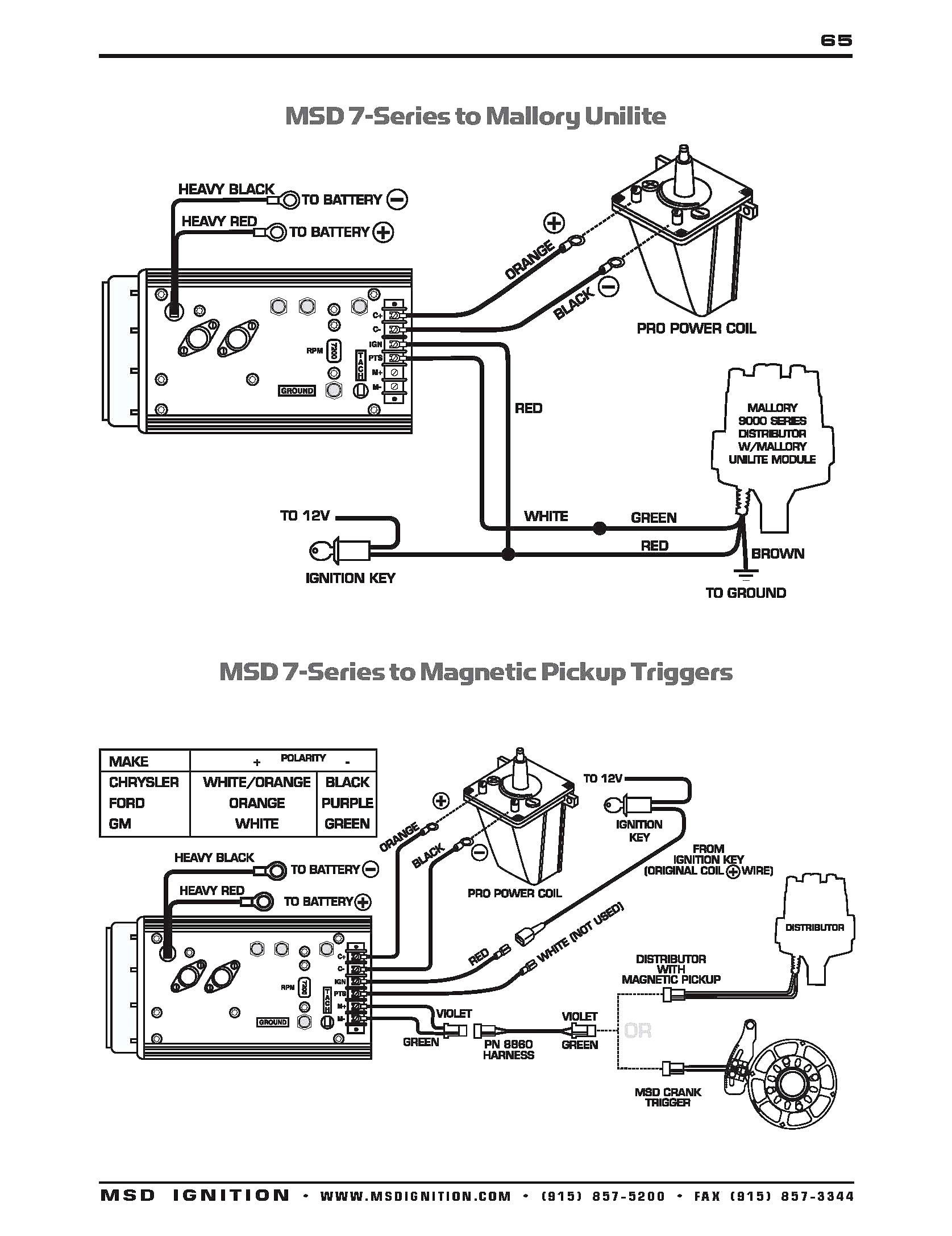
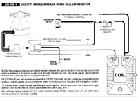
It shows the components of the circuit as streamlined forms as well as the power and also signal links between the tools. Collection of mallory ignition wiring diagram.
V8wizard
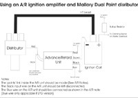
Mallory distributor wiring diagram. Whether you have the mallory unalite or dual point with or without our power amplifier you will find below a wiring diagram to suit and also the original instructions that come with the mallory distributors. Failure to use resistance wire will eventually destroy the ignition module. A wiring diagram is a simplified standard pictorial depiction of an electrical circuit. It shows the components of the circuit as simplified shapes and the power and signal friends in the middle of the devices. The purpose of an ignition ballast resistor between the ignition switch 12v and the ignition coil positive terminal is to restrict current flow through the ignition coil. Just simply click an image below for the correct instructions pack that would be supplied with your mallory distributor or for just a.
The purpose of resistance wire between the ignition switch 12v and the ignition coil positive terminal is to restrict current flow through the ignition coil. 10 start the three wires of the mallory unilite module through the hole in the nose 14 route the wires from the unilite module to the ignition coil carefully 16 follow a factory shop manual to set the timing for your particular enginewiring diagram for mallory distributer dont worry if your coil doesnt look like this american one or. Failure to use an ignition ballast resistor will. Mallory comp ss distributor wiring diagram wiring diagram is a simplified customary pictorial representation of an electrical circuit.

