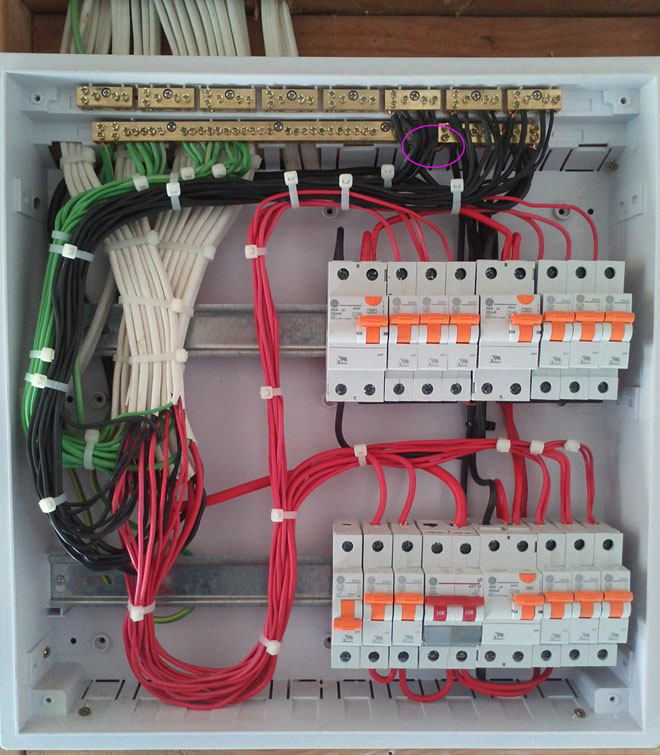
These two lines line and neutral from energy meter are connected to the double pole mcb isolator switch. Ring socket wiring diagram electrical house waring.

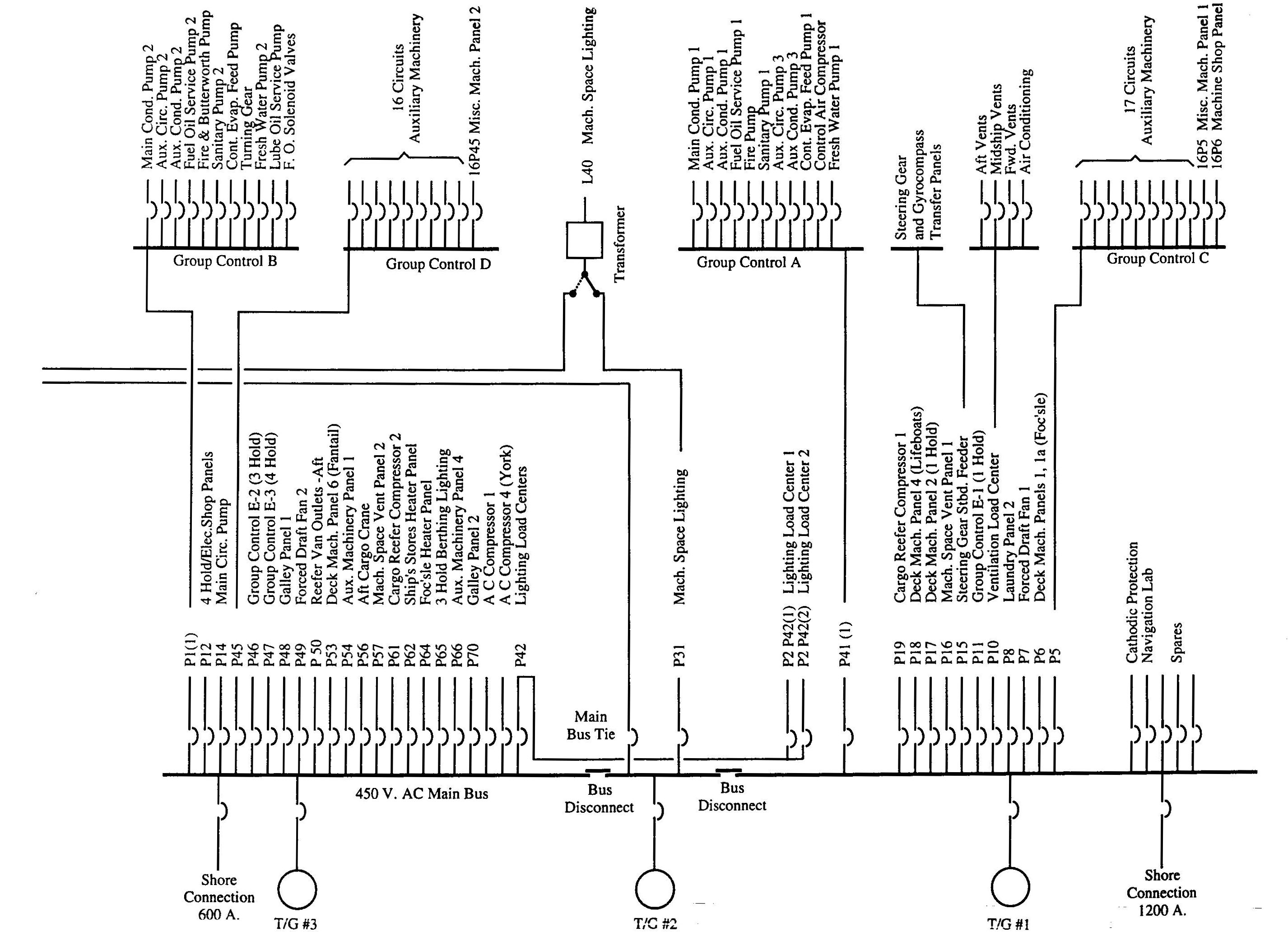
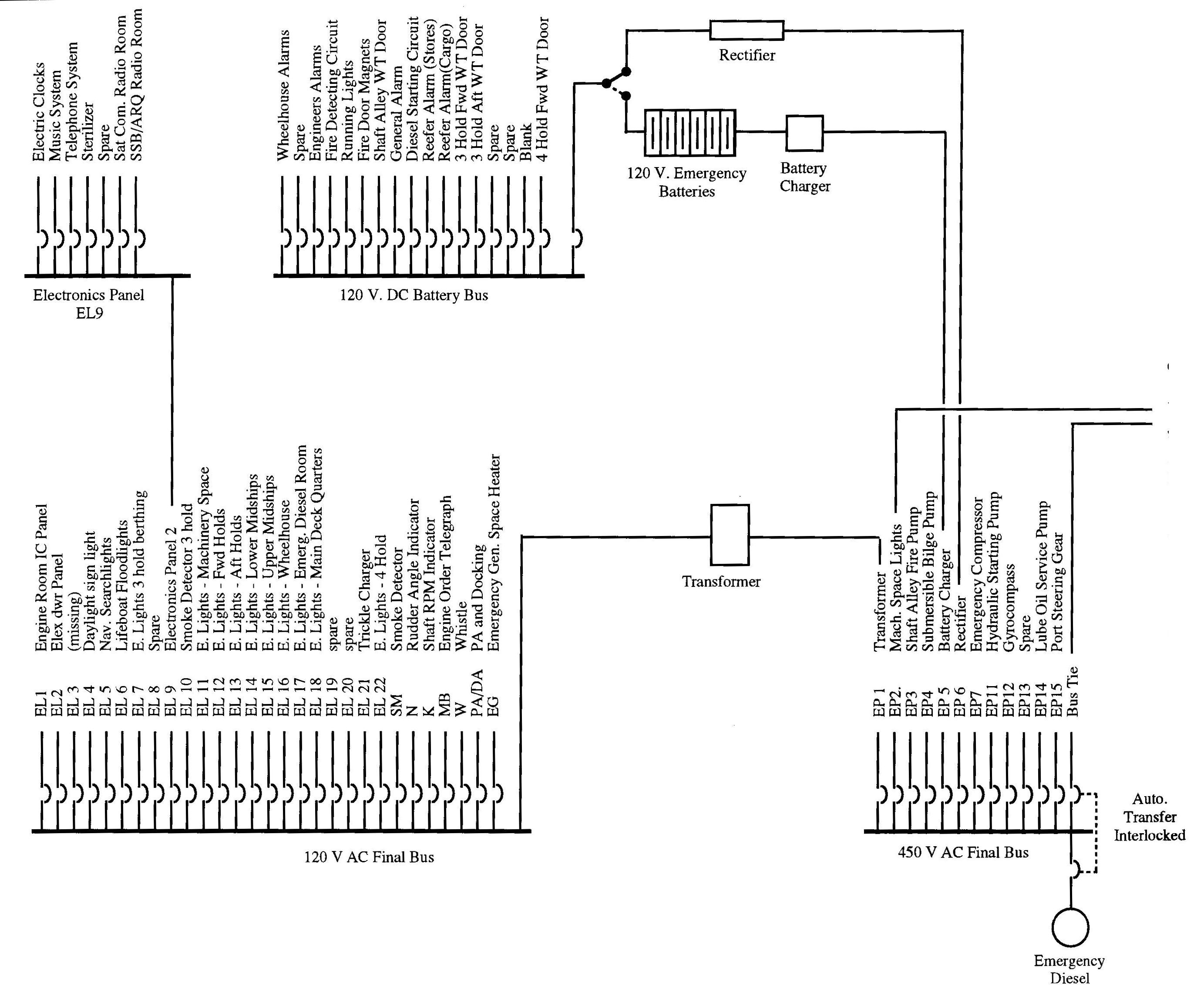
Ship Auxiliary Systems Main Switchboard Marine Knowledge
Main switchboard wiring diagram. Include schematic and wiring diagrams for all power signal and control wiring within the switchboard enclosure. Notes for switchboard metering wiring diagram 480277 volts 1wiring diagram applies to all building main switchboards utilized as the service entrance and for any sub feed switchboard if local metering or energy management metering is required. The boats bilge pump float switch. You can save this graphic file to your own device. Here only one lamp is connected from the switch box. 2all metering wiring and components shall be located in a completely isolated section from any.
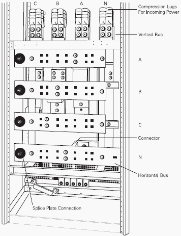
Basic electrical wiring electrical switchboard of a image i get coming from the basic household electrical wiring package. Main switchboard is a switchboard directly supplied by the main source of electrical power and intended to distribute electrical energy to. This way even if your battery switch is off if your boat starts filling with water the pump will still kick on. This is the wiring diagrams. Detail the wiring diagram for the motorized remote operated circuit breaker when the motorized remote operated circuit breaker is specified. For example the following pictorial diagram shows a two section switchboard.
In this single phase home supply wiring diagram the main supply single phase live red wire and neutral black wire comes from the secondary of the transformer 3 phase 4 wire star system to the single phase energy meter note that single phase supply is 230v ac and 120v ac in us. A wiring diagram is a simple visual representation of the physical connections and physical layout of an electrical system or circuit. The other pole of switch s1 is connected to the lamp. Detail grounding balls and associated bus when grounding balls are specified. Siemens basics of switchboards. Simplified drawings such as one line block or pictorial diagrams are often used to show the circuits associated with a power distribution system.
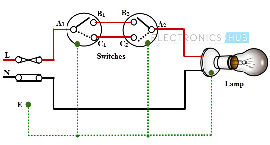
We also have some more pics associated to basic household electrical wiring please see the pic gallery below click one of the pics then the. Its pretty standard in boat wiring to bypass the main battery switch for one thing. In the below wiring diagram one pole of the both spst single pole single throw switches s1 s2 are connected to the phase line of the supply. It shows how the electrical wires are interconnected and can also show where fixtures and components may be connected to the system. Please right click on the image and save the pic. And the switch s2 is connected to the phase pole of the three pin socket.
