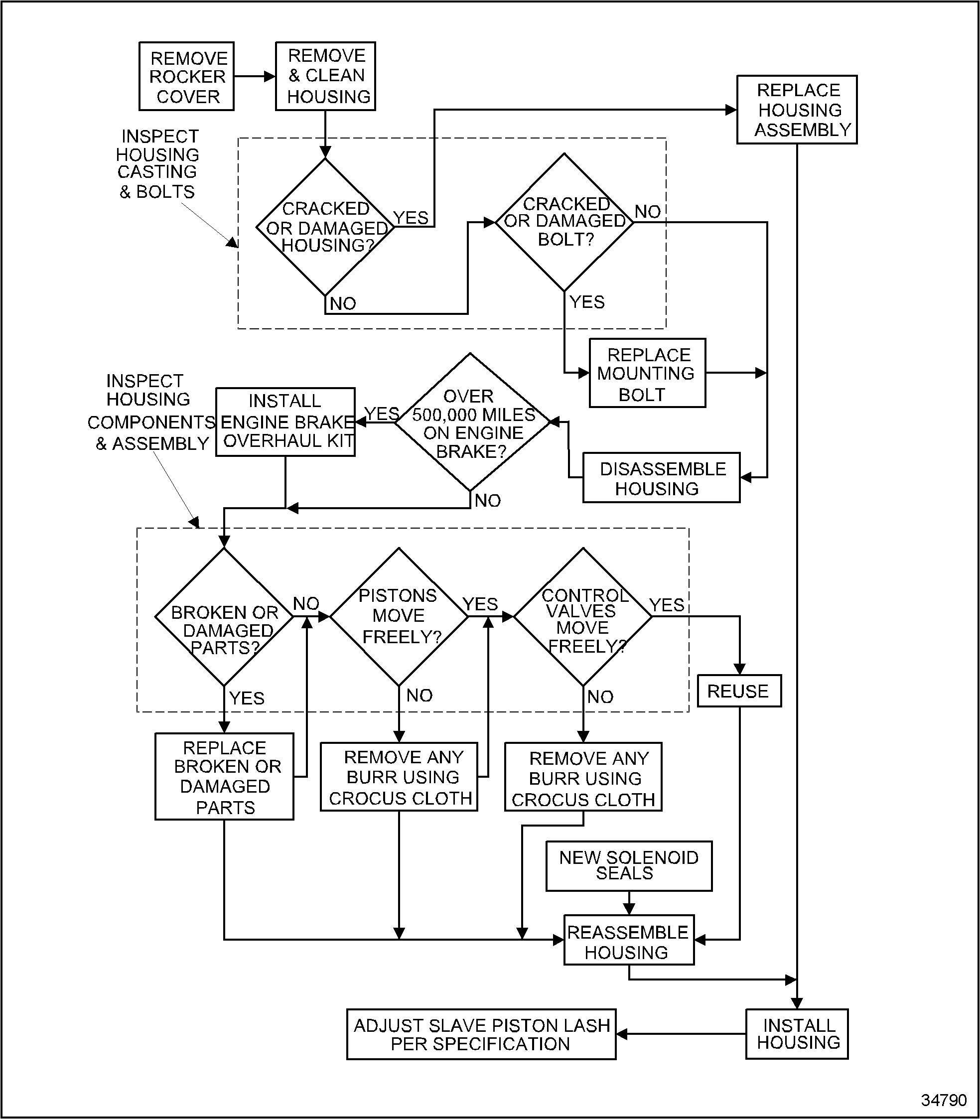
Brake housing installation 5 housing placement 5 valve and injector adjustments 5 slave piston lash adjustment 6 housing wiring 7 final housing installation and test 7 chassis wiring 7 final test 7 3. Theory and operation of the jake brake engine brake duration.
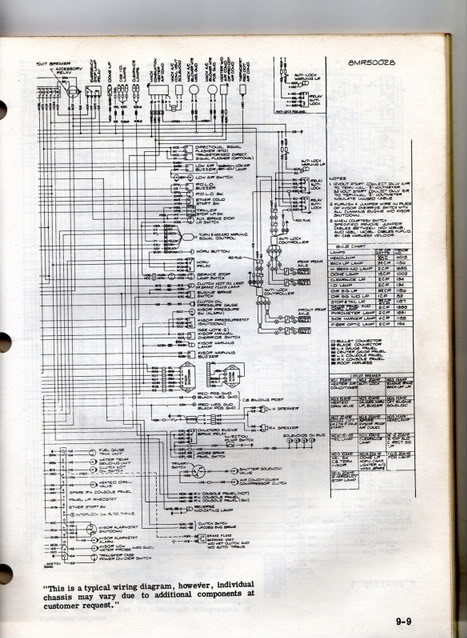
Mack Fuse Diagram Wiring Schematic Daihatsu Rmnddesign Nl
Mack jake brake wiring diagram. Engine brake diagram this engine brake diagram outlines how engine brakes work. The tools and wizards will help you fill in all necessary information to locate the right tune up kit and application for your trucks jake brake. Cutting into wiring harnesses is not recommended as it may affect can bus messaging. Changing brakes on a big truck. Always check the latest information at the wiring diagrams location. It shows the components of the circuit as simplified shapes and the capacity and signal connections in the midst of the devices.
Jake brake wiring diagram wiring diagram is a simplified tolerable pictorial representation of an electrical circuit. Aa spf44a spx03ea3 fb2a1 08 ag0 b a17b2 ai4 c frcj3c5 aq1 b mcsca9 f61a1 08 hb2 d a131ba4 f15a1 50 bi3 c x210aad f87 15a cust. Engine brake maintenance 8 theory of operation 8 solenoid valve 9 control valve 9 auto lash adjusting screw 10 slave piston 10 master piston 11. Visit howstuffworks to check out this great engine brake diagram. You may also use our part number cross reference tool to cross reference a specific part number or print off a complete list by manufacturer. A b f71 15a center pin hot a b f60 30a hvac fan a b f61 5a lvd sens vendor ttu a b f76 30a 3968162 a f05 30a lecm4 b f06 20a rh sleeper pwr ports console b.
See new video easier better. Power distribution frc 12 wiring diagram. Utilization of body builder connectors ordered and provided by mack is strongly recommended as your power lighting and ground source for body installation pto installation and operation.


