Expandible with exp modules code. If the ethernet to serial converter has a rs 232 interface port then use the same wiring diagrams suggested for the com port of the pc.

Lovato Rgk 60 User Manual
Lovato rgk60 wiring diagram. This solution provides a reliable and permanent connection suitable for any industrial ambient for distances up to 1 km. Two way switch circuit diagram. Wiring mode 1 2 or 3 phases with or without neutral current inputs rated current ie 5a. Mazza 12 24020 gorle bg italy tel. Sterownik agregatu prądotwórczego lovato rgk60 elektroda. Product data sheet of automatic mains failure amf gen set controller 1224vdc graphic lcd with rs485 port and usboptical and wi fi point programming port on front canbus port ip65.
Rgk60 rgk50 rgam20 rgam4 generator set control units. Rj45 wall socket wiring diagram. This type of connection may entail some difficulty for users. Refer to the wiring diagram given in appendix a for the relative connection. Connection via standard modem when there is a long distance between pc and rgam a remote control can be established using a set of. Rca plug to speaker wire diagram.
Sterownik agregatu prądotwórczego lovato rgk60 7679528966. Lovato electric rgk600 instruction manual 39. It shows the components of the circuit as simplified shapes and the facility and signal associates amid the devices. Rgk60 help g sales department. Lovato rgk60 wiring diagram. Page 34 schemi di connessione wiring diagrams schema di collegamento per gruppi elettrogeni trifase con schema di collegamento per gruppi elettrogeni trifase con ingresso ingresso w pick up wiring diagram for three phase generating set with.
Lovato rgk60 genset controller rgk x01 real time clock rs485. Need user manual for lovato rgk60 fixya. Control solutions for industry via don e. Aprilia rs 50 wiring diagram. 39 035 4282354 fax 39 035 4282400 lovato electric spa. Generating sets controllers lovato rgk60.
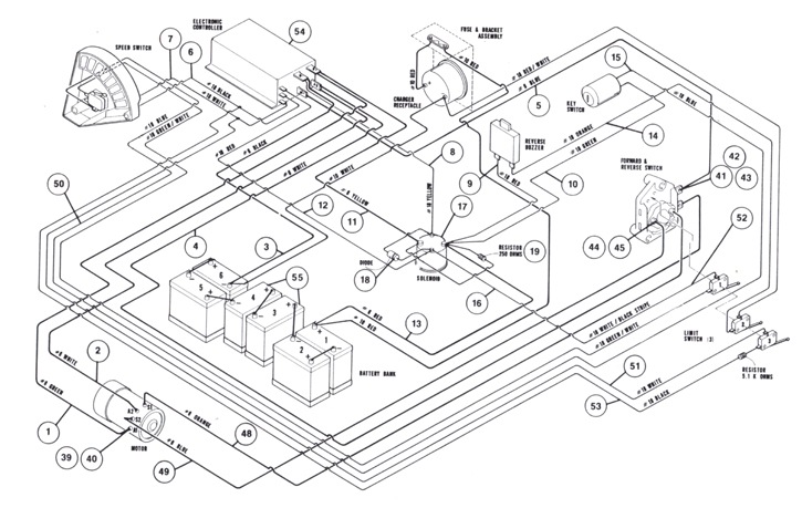
Resistive load bank wiring diagram. Lovato rgk60 wiring diagram dcre 5 dcre 7 dcre 12 electric lovato rgk60 wiring diagram wiring diagram is a simplified agreeable pictorial representation of an electrical circuit. 90 one pole onoff switch91 two pole onoff switch 10 three pole onoff switch 92 four pole onoff switch 51 1 pole changeover switch with 052 2 pole changeover switch with 0 01 01 01 01 021 021 number of wafers. Power antenna wiring diagram. Modem through the cable supplied by lovato. Also see for lovato electric rgk600.
Yamaha g1 gas wiring diagram. 60 number of wafers. Lovato electric introduces its controller for sprinkler type fire fighting gateway data logger lovato electric is introducing its own solution for access to cloud based energy rgk750 automatic mains failure genset controller the range of genset controllers has been expanded with the general purpose relays hr series.


