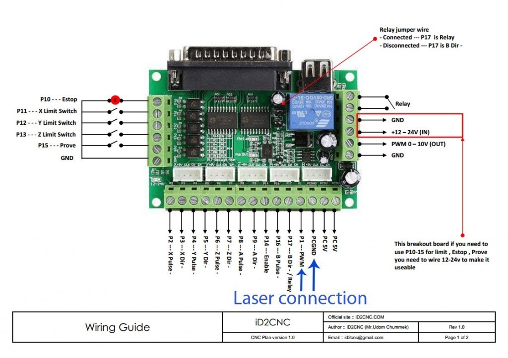
Exmark manufacturing was incorporated in may 1982 as an independent manufacturer of professional turf care equipmentthe company began its manufacturing operation with seven employees in a garage type building located just south of beatrice nebraska. Usually all our lasers work on fan 1 pin 3d printer or a spindle pin on a cnc machine.

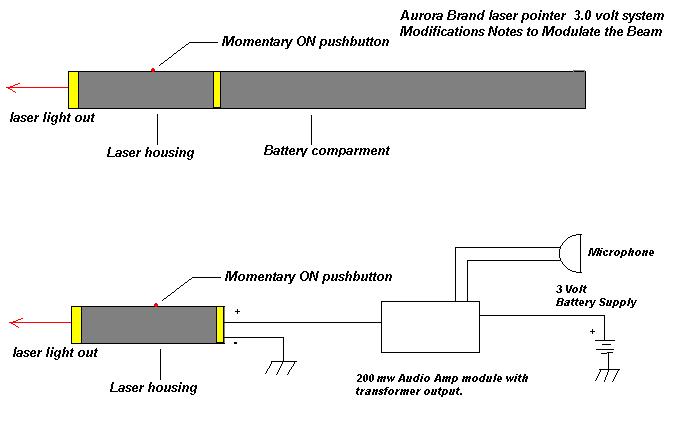
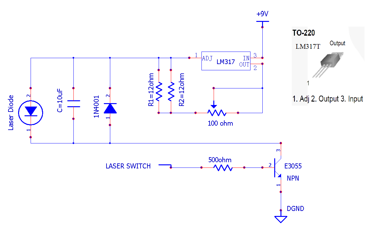
Kf 6921 Laser Pointer Diode Wiring Diagram Schematic Wiring
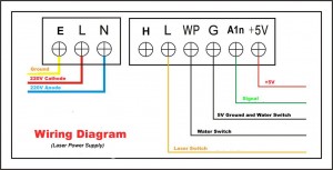
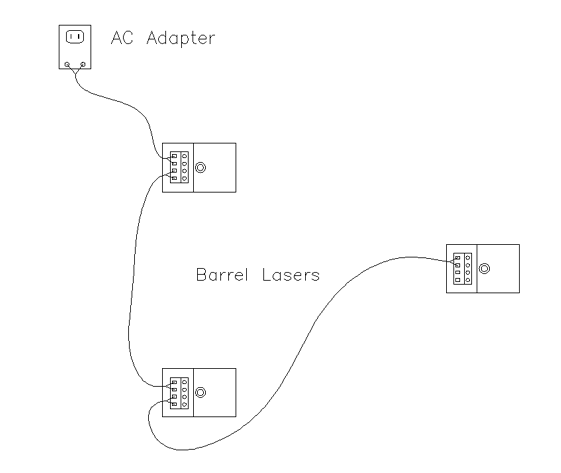
Laser wiring diagram. Co2 laser power supply wiring diagram download here it is compatible with most of chinese other brands co2 laser power supply. This is a quick demonstration on the thunder laser nova 35 about one way the lightburn camera functions can speed 12082019 thunder laser air assist control. May 29 grbl pin diagram. Diagrams and order genuine details about exmark lazer z hp wiring diagram has been uploaded by ella brouillard and tagged in. Safety is most important. If you do it wrong then you can be electrocuted.
The high voltage and power combination can be lethal. How to test and set a chinese china made co2 laser power supply to get long life from your co2 laser tube for your laser engraving and laser cutting machine system. You might already have a proper laser pin. Check a pwm pin. Be safe when performing this project. Exmark lazer z hp user manual schematics electrical diagram kohler ignition switch exmark gardening equipment.
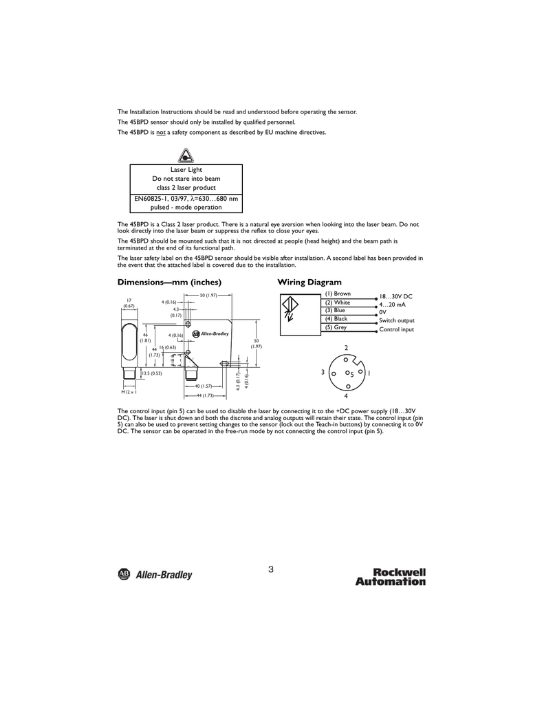
It is very easy to mount hook the laser to your cnc machine or 3d printer. We supply with all compatible connecting mounts. A wiring diagram is a streamlined conventional photographic representation of an electric circuit. It shows the elements of the circuit as simplified shapes as well as the power and signal links between the devices. Assortment of exmark lazer z wiring schematic. Explore detailed wiring diagrams.
The main difference is the newer power supply contains a secondary green terminal block on the front of the power supply next where the hard leads are connected. So far i havewiring diagrams for the laser power supply will be mostly the same with the updated power supply. I numbered the connections on both diagrams to make sure the wiring changeover went smoothly see 205 using a copy of the wiring diagram cut out connection labels and attach them to the wires before removing the controller to avoid any confusion when making the change over.
