02 9797 0092 e. Kraus naimer pty.
3 Phase Drum Switch Wiring Diagram Mustanggh 7 Mareikekirsch De
Kraus naimer ca11 wiring diagram. This model has been replaced with the kraus naimer model c26. 1 905 738 1666 f. Free next day delivery. 1 732 560 1240 e. The color code is. Kraus naimer is the world market leader within the field of cam switches.
Qualified engineering and customer support consultancy local stock and on site assembly facilities guarantee quick and competent service. Wiring diagram kraus naimer ca10 datasheet cross reference circuit and application notes in pdf format. 1 905 738 9327 e. The c series switch represents the classic cam switch by kraus naimer. Kraus naimer ca11 wiring diagram copy of electrical inventory kraus naimer ca11 wiring diagram wiring diagram is a simplified satisfactory pictorial representation of an electrical circuit. Kraus naimer ltd.
Founded in 1907 in vienna austria in a small cellar we now support sales companies and sales partners from our headquarters in. Kraus naimer inc. It shows the components of the circuit as simplified shapes and the skill and signal connections amongst the devices. 1800 567 948 f. Kraus naimer ltd. The ca series with finger proof terminals from 10 a to 32 a is ideally suited for many standard applications where industrial controls instrumentation and electric.
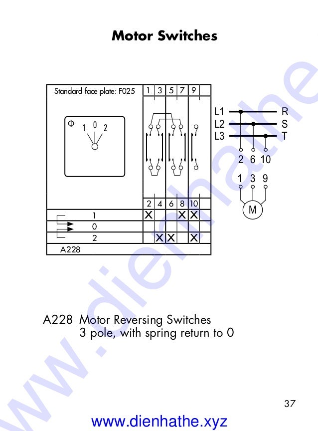
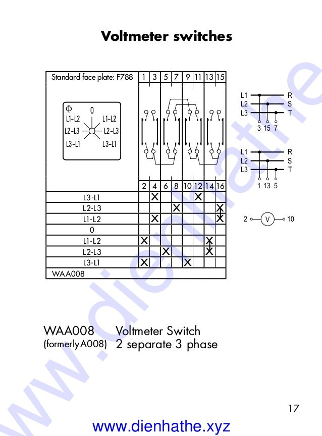
14a 240 v this auction is for an unused kraus naimer cam switch. 760 new brunswick road somerset nj 08873 usa p. 379 liverpool road nsw 2131 ashfield australia p. Wiring diagram off on 2 4 6 3 1 7 5 11 9 man off auto wiring diagram 1 3 5 7 9 11 man auto wiring diagram 2 6 10 m1 m2 m3 5 7 1 m 1 3 5 single phase 6 10 2 three phase l1 l2 l3. Comes with wiring diagram and installation manual. Flexible awg wires without sleeve.
Kraus naimer f the full code would now be ca10 a e. Three position each set of poles has an adjustable cam which changes onoff sequence must be disassembled to change sequence. 219 connie crescent unit 13a l4k 1l4 ontario canada p. Kraus and naimer ca10 wiring diagram wiring diagram is a simplified pleasing pictorial representation of an electrical circuitit shows the components of the circuit as simplified shapes and the knack and signal friends amongst the devices. With specific models for all current ratings it offers an ideal solution for a wide variety of applications.

