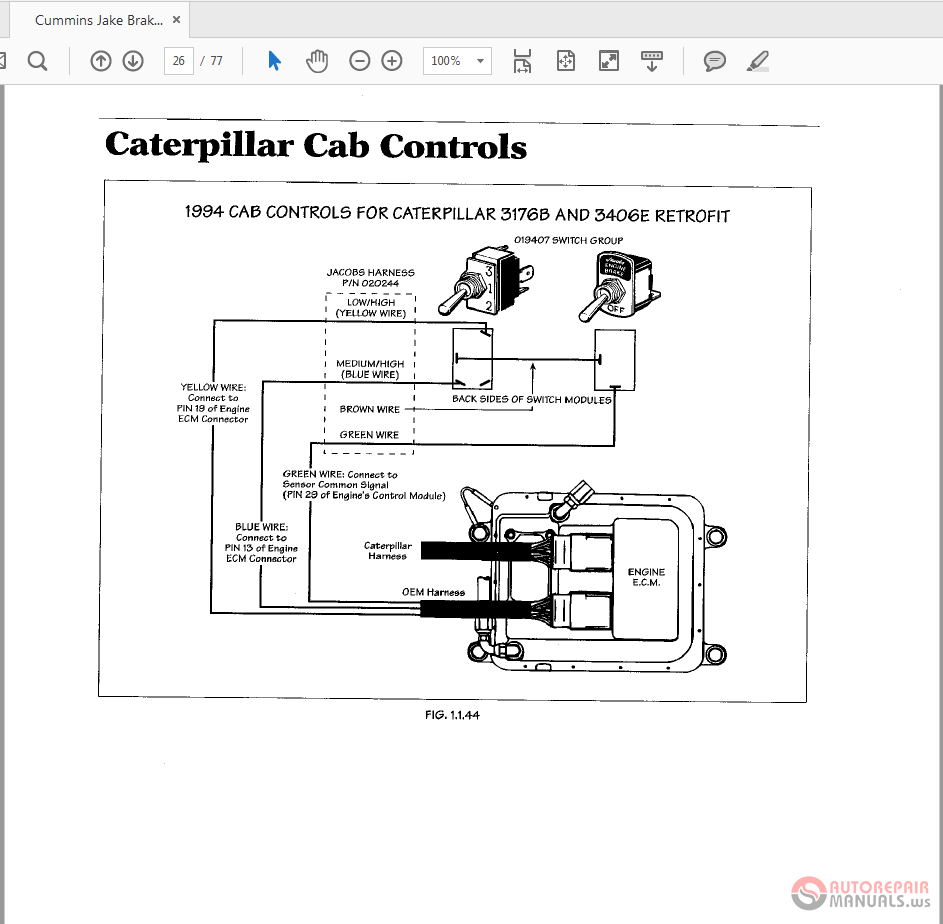
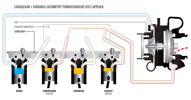
Based on the wiring diagrams that jacobs provides on their website you can see that the switch has a physical connection between the two middle terminals where the 12v goes and one top and. The tools and wizards will help you fill in all necessary information to locate the right tune up kit and application for your trucks jake brake.

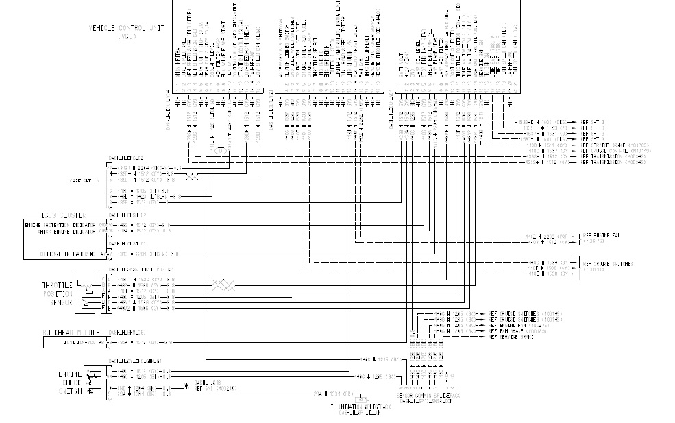
Wrg 1635 Jake Brake Switch Wiring Diagram
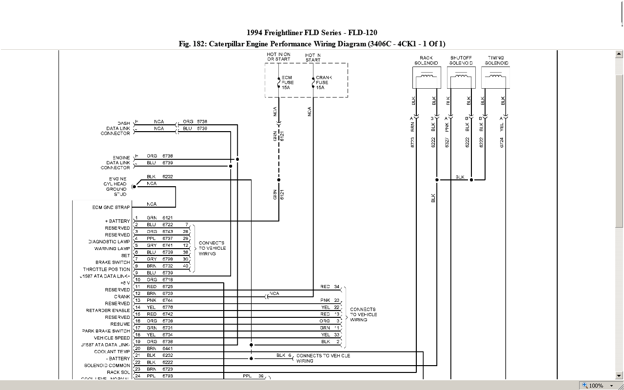
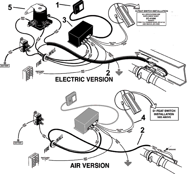
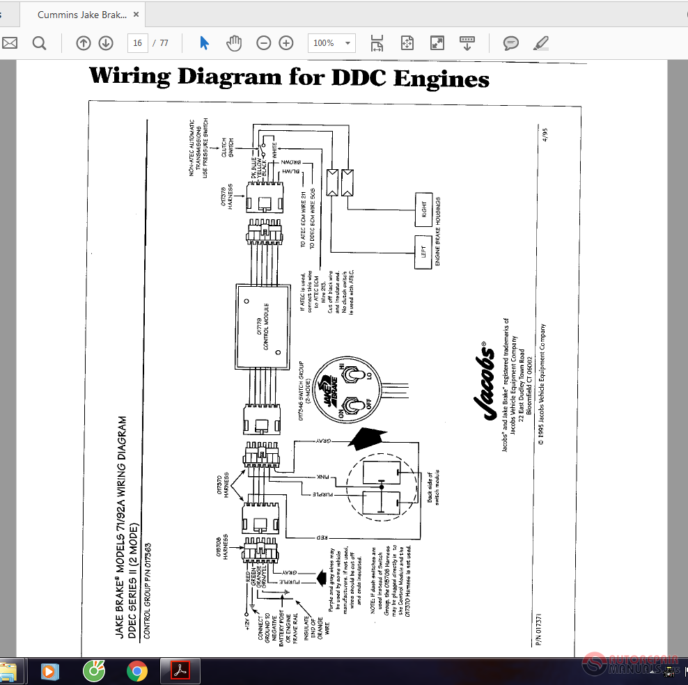
Jake brake switch wiring diagram. 1986 peterbilt 359 1980 freightliner flc 12064. You may also use our part number cross reference tool to cross reference a specific part number or print off a complete list by manufacturer. Posted by kblackav8or 7 years ago. Jake brakemodels 7192a wiring diagram ddec series ii 2 mode control group pn 017363 12v red green orange grnyel purple gray connect ground to negative battery post or engine frame rail insulate end of orange wire purple and gray wires may be used by some vehicle manufacturers. Jake brake wiring diagram wiring diagram is a simplified tolerable pictorial representation of an electrical circuit. If not used wires should be cut off and ends insulated.
Otherwise the arrangement will not function as it ought to be. Its a kw w. Each part should be placed and linked to different parts in particular way. Someone have one they can post. Anybody have a wiring diagram for the jake brakes on a cat b mechanical. It shows the components of the circuit as simplified shapes and the capacity and signal connections in the midst of the devices.
I know there needs to be a jumper wire on the dpdt switch. I am going out to work on other wiring but i will be hoping to do this tonight. Brake housing installation 5 housing placement 5 valve and injector adjustments 5 slave piston lash adjustment 6 housing wiring 7 final housing installation and test 7 chassis wiring 7 final test 7 3. Cummins jake brake wiring diagram. Ok i have been doing a lot of reading and research on jacobs engine brakes and cannot figure out how the wire the dpdt switch for 3 stage of operation. Kenworth w900 wiring diagram 1984 kenworth w900 wiring diagram 1999 kenworth w900 wiring diagram 2000 kenworth w900 wiring diagram every electrical structure consists of various different pieces.
You dont have permission to rate. Engine brake maintenance 8 theory of operation 8 solenoid valve 9 control valve 9 auto lash adjusting screw 10 slave piston 10 master piston 11. The wire then goes to a micro switch mounted at the clutch via a inline fuse this micro switch is normally mounted in a arm operated box th at tuches the clutch pedal so the engine brake is tempry switched off when changin gears then the wire goes to the micro switch at the buffer at governer this is a very presise adjustment.
