It reveals the parts of the circuit as streamlined forms and the power and signal connections in between the gadgets. A wiring diagram is a simplified standard pictorial depiction of an electric circuit.

Iota Ul Listed Constant Power Led Emergency Drivers For Field
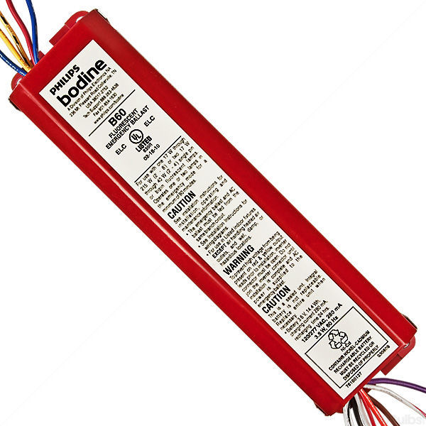
Iota emergency ballast wiring diagram. Iota emergency ballast wiring diagram image building circuitry layouts show the approximate places as well as affiliations of receptacles illumination and irreversible electrical services in a structure. Iota life saving emergency lighting solutions and powerful acdc convertercharger designs. The diagrams are categorized primarily according to the number of. The i 40fluorescent emergency ballast from iota engineering allows the same fixture to be used for both normal and emergency operationin the event of a power failure the i 40switches to the emergency mode and operates oneof the existing lamps for 90 minutesthe unit contains a battery charger and inverter circuit in a single can. Refer to the wiring diagrams on the back page for the appropriate wiring of lamps and ballast. For additional wiring diagrams consult customer service.
We develop and manufacture premium solutions for your emergency lighting needs and battery charging applications that wont leave you guessing. It shows the components of the circuit as streamlined shapes as well as the power as well as signal links in between the tools. If a diagram cannot be found within this selection consult customer service. August 3 2019 by larry a. When it matters most iota products perform. If you cannot find a diagram that matches your particular application contact customer magnetic normal power factor ballast parallel lamps emergency.
Ballast emergency ballast relay how to use the emergency ballast wiring guide this document has been customized to contain a wide library of individual dia grams for various installation applications. Wiring refer to the wiring diagrams on the back page for the appropriate wiring of lamps and ballast. Wiring diagrams select an available diagram from the list below. The i 232fluorescent emergency ballast from iota engineering allows the same fixture to be used for both normal and emergency operationin the event of a power failure the i 232switches to the emergency mode and operates twoof the existing lamps in parallelfor 90 minutesthe unit contains a battery charger and inverter circuit in a single can and can be mounted in the. Wellborn collection of iota i 24 emergency ballast wiring diagram. Emergency the i and ac.
Ballast must be on the same branch circuit. Adjoining wire courses might be revealed approximately where certain receptacles or components should be on an usual circuit. April 3 2019 by larry a. 4alling the threaded body test switch tbts inst. If you cannot find a diagram that matches your particular application contact customer service or call 1 800 866 iota with details regarding your application. Collection of iota i320 emergency ballast wiring diagram.
Install in accordance with the national electrical code and local regulations. A wiring diagram is a streamlined conventional pictorial representation of an electrical circuit.


