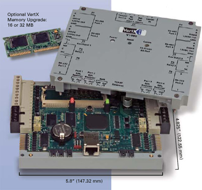
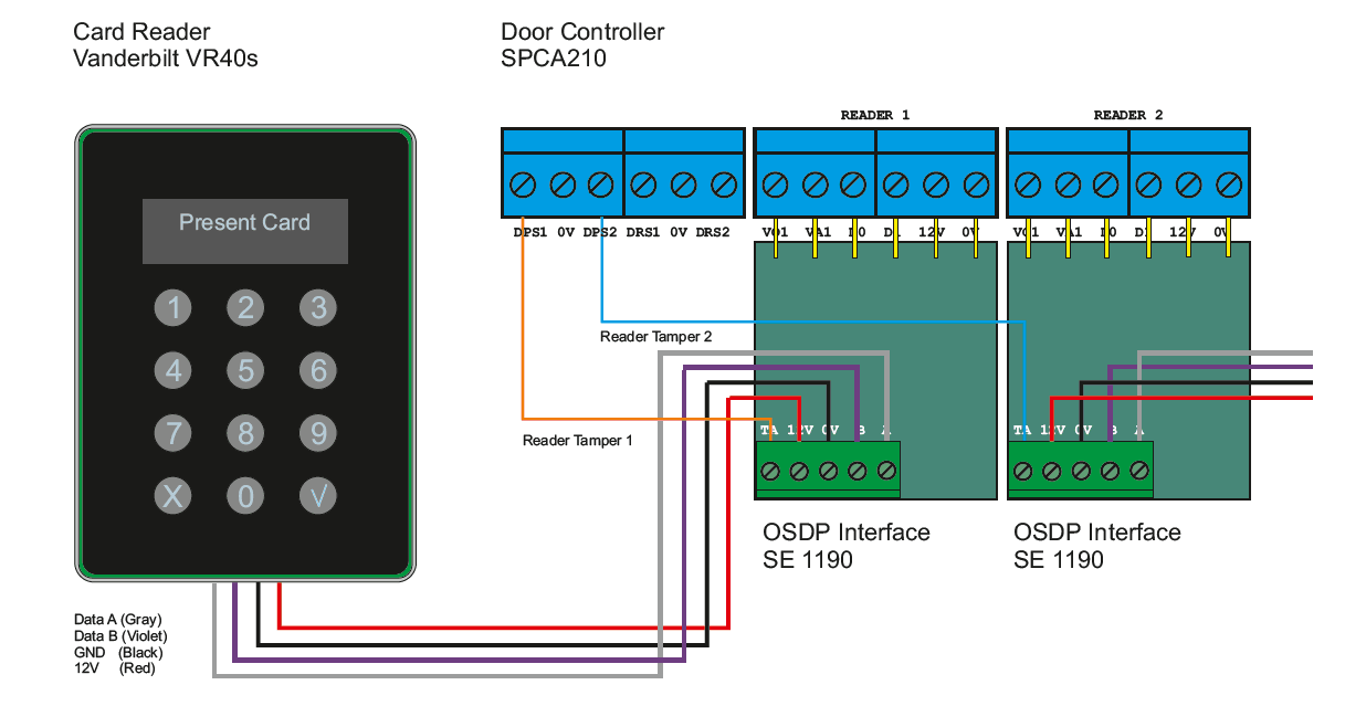
The maximum cable length is 2000 ft. Reader port 1 can support up to eight 2 wire rs 485 remote serial io devices using msp1 protocol or up to two osdp devices.

Access Control By Jules Bartow Goldvein Power Amp Automation
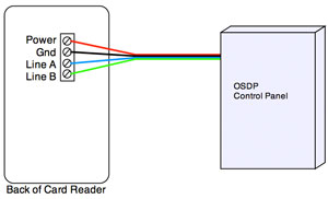
Hid osdp wiring diagram. Multiclass sereaders are part of hid globals iclass se platform for highly secure adaptable and interoperable access control. Once wiring is complete the readers can now be brought online. Osdp developer tool kit the revolutionary modular design of hid globals iclass se platform readers and the osdp upgrade module allow users to easily upgrade their systems by plugging in the osdp upgrade module into existing or new readers. If two osdp devices are used reader port 2 will not support a third reader. For multiple osdp reader installations the readers must be brought online. Pair over all shield and ul approved belden3107a or equivalent osdp linear dc power supply metal or plastic junction box security tool for anti tamper screw hid 04 0001 03 drill with various bits for mounting hardware mounting hardware reader spacer when mounting on or near metal or metal junction boxes.
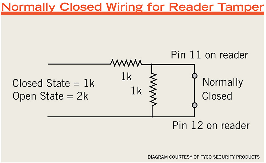
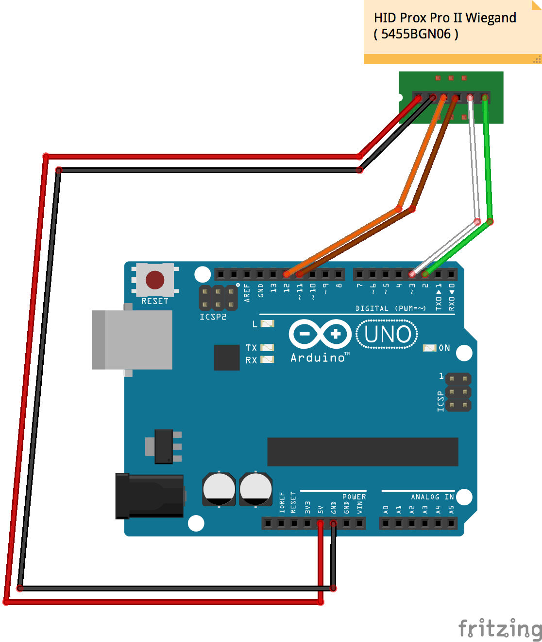
The wiring diagram above depicts how the wiegand protocol requires homerun cable pulls from the control panel to individual peripheral devices. Support osdp secure channel protocol for secure communications central management of your se readers. Ssis master technician series wiring diagram. The following circuit diagram shows the iclass optical tamper. Dynamic multiclass se 1356 mhz contactless readers support a broad array of credential technologies and a variety of form factors including including cards fobs and mobile devices. Nsc 200 to hid osdp reader wiring.
Depending on wiring installation for example using additional set of wire s and resistance the tamper is also active if the reader is powered off. Upon reception of a reader status report request. Hid global hid the hid bric logo the chain design and piclass are trademars or registered trademars of hid global assa ablo ab or its afiliates in the us. Wiegand vs osdp wiring diagram created date. A wiring diagram is a simplified traditional pictorial representation of an electric circuit. During a tamper state the im alive 2 message is inverted.
For multiple hid osdp readers that will be connected to the nsc 200 the wiring will have to be daisy chained as shown. If only one osdp device is configured then reader port 2 is available for a second reader. Assortment of hid card reader wiring diagram. Osdp is fl exible to support either homerun cable pulls or the daisy chain methodology depicted on the right. It shows the parts of the circuit as simplified forms as well as the power as well as signal links in between the devices. And other countries and ma not be used ithout permission.
