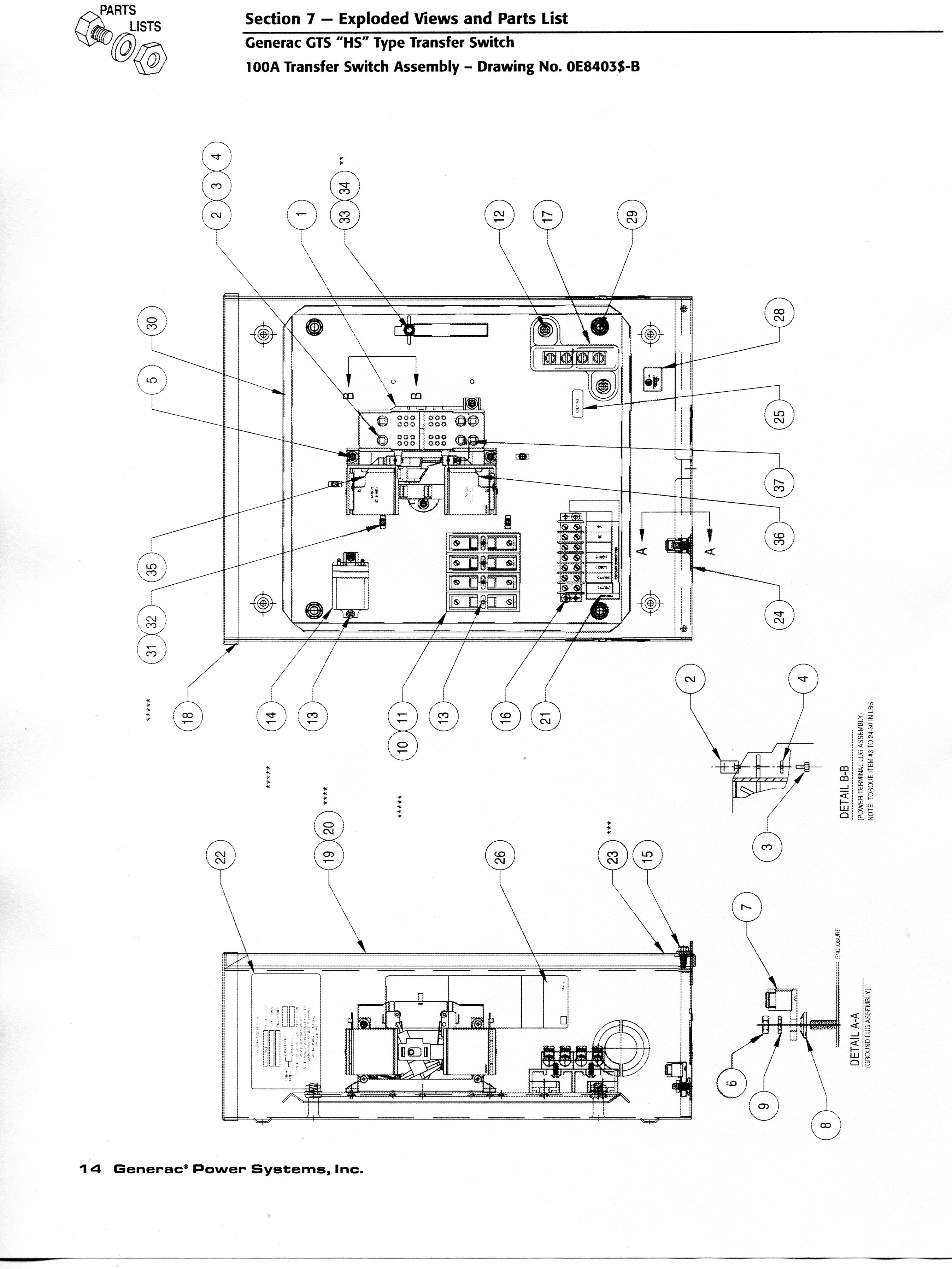
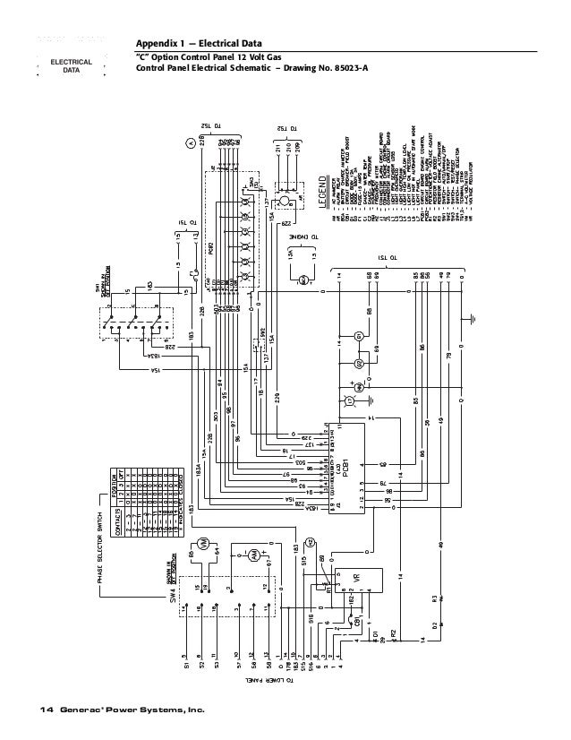
Wellborn assortment of generac gts transfer switch wiring diagram. Generac gts transfer switch wiring diagram download generac manual transfer switch wiring diagram sources exactly what is a wiring diagram.

Read Or Download Bodine Electric Motor Wiring Diagram For
Generac gts transfer switch wiring diagram. It demonstrates how the electrical cords are adjoined and also could likewise. A wiring diagram is a basic visual depiction of the physical connections and physical design of an electric system or circuit. About the gts transfer switch generac gts transfer switches feature status lights that indicate switch position and source status a programmable weekly exerciser independent voltage pickup and dropout adjustments and utility monitoring to protect against utility phase loss conditions. Assortment of generac gts transfer switch wiring diagram it is possible to download at no cost. Section 2 installation generac gts w type transfer switch figure 24 connection diagram 3 phase with neutral shown typical recommended wire gauge sizes for this wiring depends auxiliary contacts on the length of the wire as recommended below. Assortment of generac 200 amp automatic transfer switch wiring diagram.
When an automatic transfer switch is installed for a standby. A wiring diagram is a simplified standard pictorial depiction of an electrical circuit. It reveals the elements of the circuit as simplified forms and the power as well as signal links between the tools. Wiring diagrams help technicians to see how the controls are wired to the system. Please download these generac gts transfer switch wiring diagram by using the download button or right click selected image then use save image menu. February 2 2019 by larry a.
A wiring diagram is a streamlined conventional pictorial representation of an electric circuit. And get immediate medical help. Wiring diagrams and electrical schematics are provided in. Generac gts w type transfer switch installing the switch includes the following proce dures. If desired you have access to auxiliary contacts on the maximum wire length. It reveals the components of the circuit as streamlined shapes and the power and signal links in between the tools.


