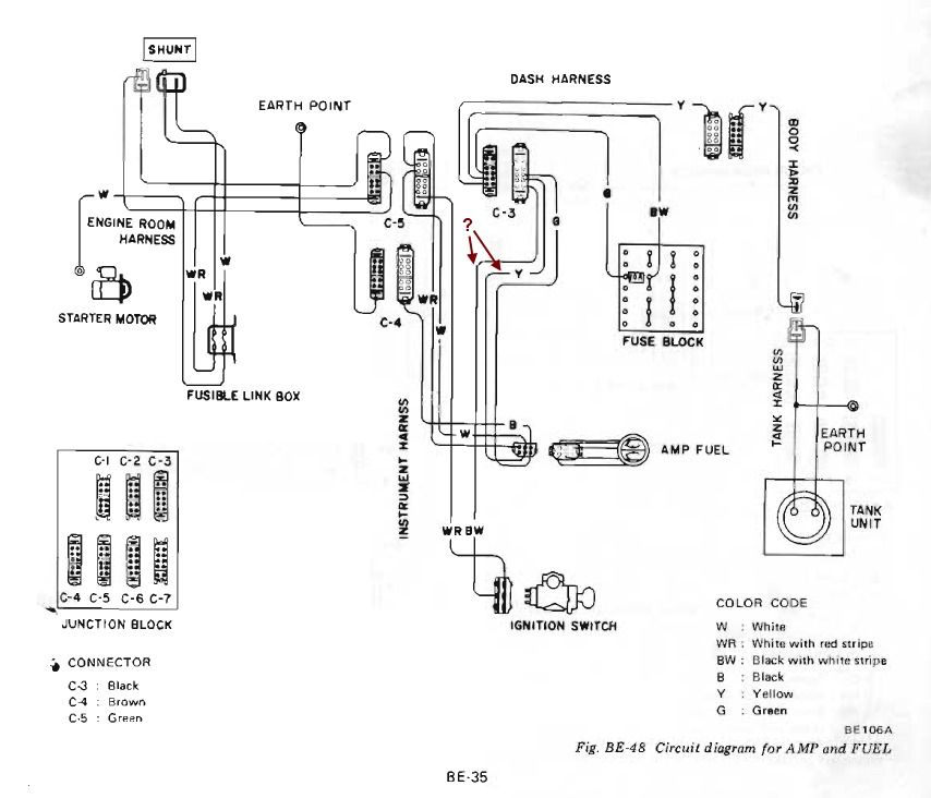
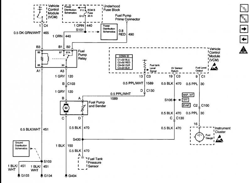
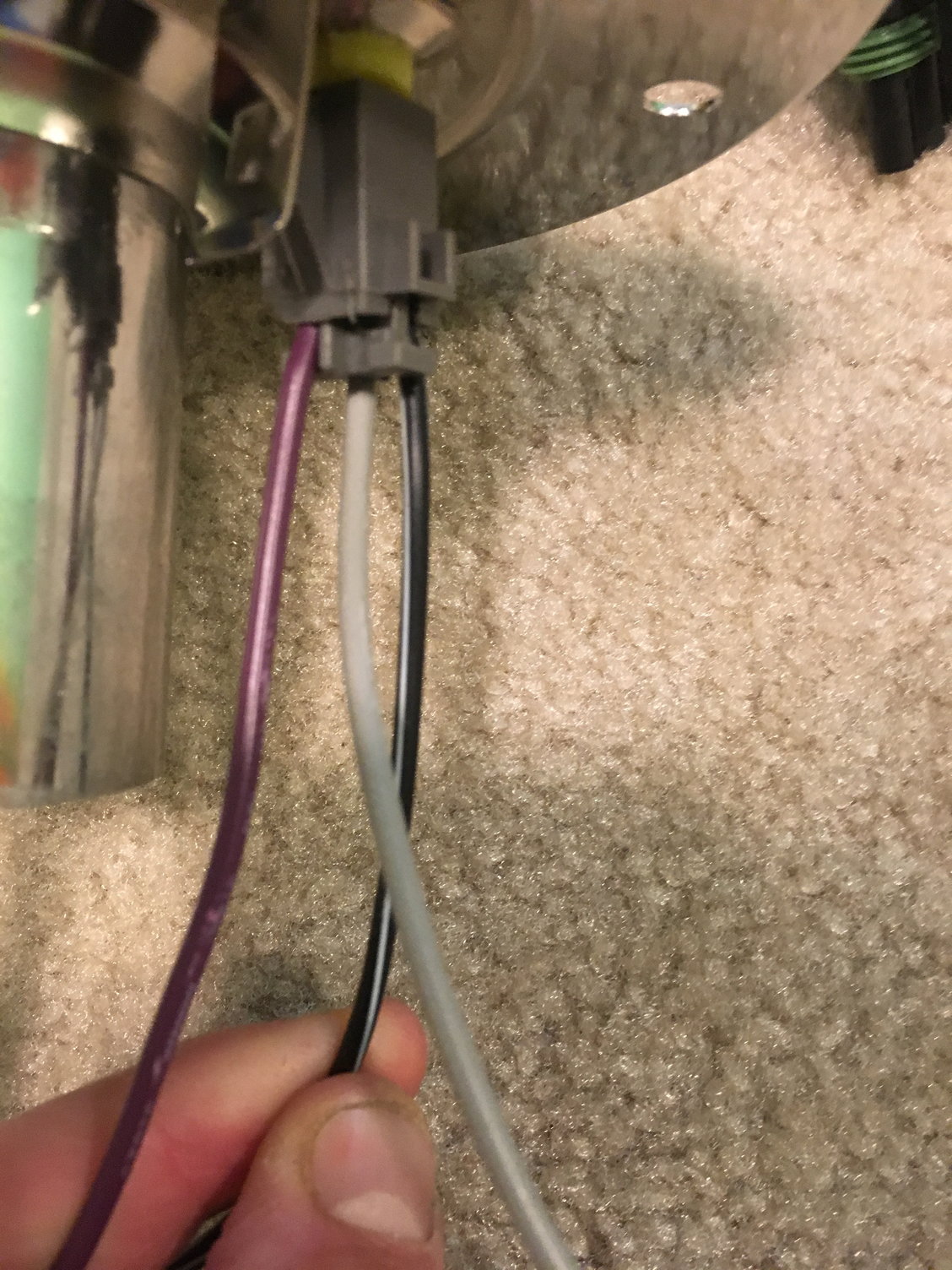
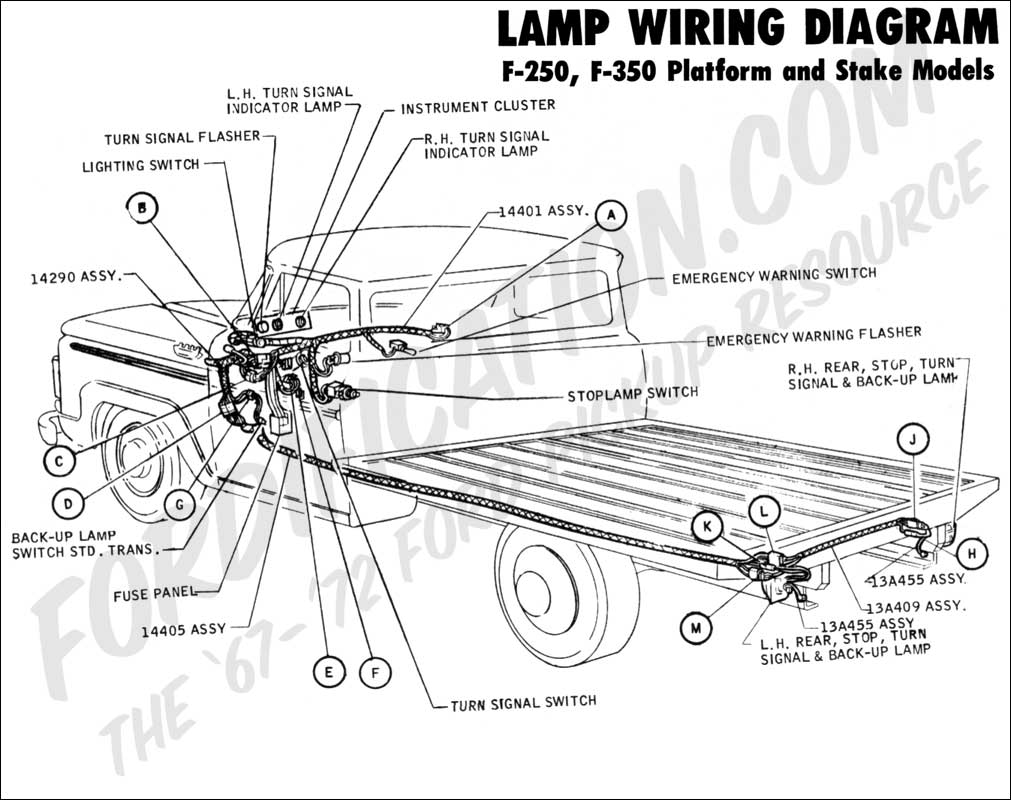
The fuel tank should be grounded and the sender wire pink should be connected to the sender terminal on the sending unit this is the correct wiring. Assortment of fuel gauge sending unit wiring diagram.
Fuel Sending Unit Wiring Mustang Forums At Stangnet
Fuel sending unit wiring diagram. The other wire runs to ground. A first appearance at a circuit representation might be complex yet if you could check out a metro map you can review schematics. Super easy boat wiring and electrical diagrams step by step tutorial duration. It shows the elements of the circuit as streamlined forms as well as the power as well as signal links between the devices. Tiny boat nation 318010. There are two types of sending units.
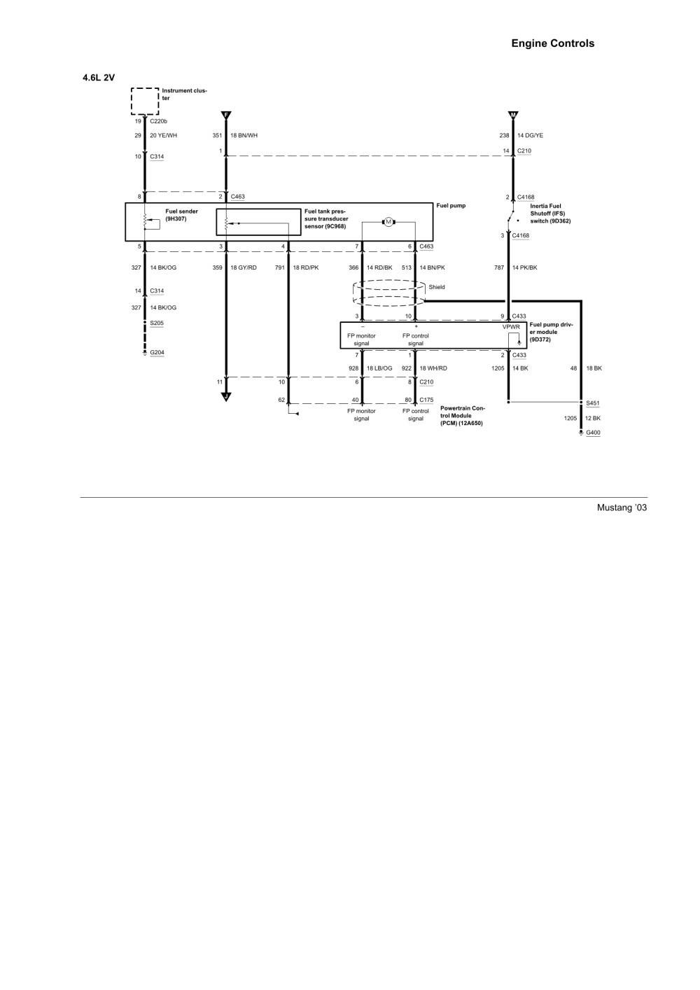
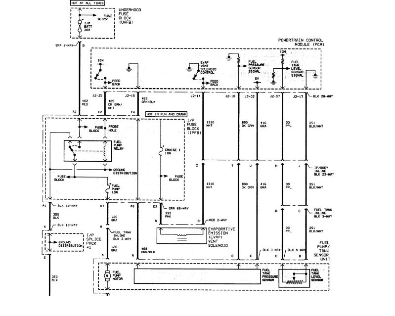
Fuel sending unit wiring diagram you will want an extensive skilled and easy to understand wiring diagram. The fuel gauge reads the resistance to ground check the wires on the back of the gauge pink to s terminal and black to g terminal. I attached the wiring diagram for the fuel pump. Marine fuel sending unit wiring diagram circuit maker arduino new a beginner s guide to circuit diagrams. The sending wire leads off the center post. How to test fuel sending unit and gas gauge chevelle gm duration.
Obtaining from point a to direct b. My new sending unit installed. Literally a circuit is the course that allows. The new fuel gauge. Looks like the. The wire marked runs to the engines ignition switch.
The sending unit will ground through the mount screws. The older float style which uses a magnet embedded in a float that resides in a tube sending readings of how high in the tank it is floating and there is the newer style that measures electrical resistance of the volume of fuel in the tank. Need the wiring colors of the connector for the fuel pumpsending unit. The fuel sending unit is responsible for what the fuel gauge on your vehicle reads. Fuel gauge sending unit wiring diagram. With this sort of an illustrative guidebook you are going to be able to troubleshoot prevent and total your assignments without difficulty.
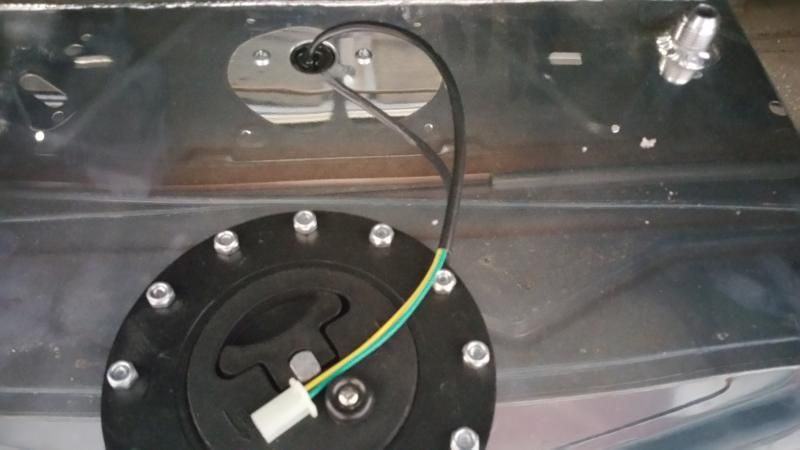
Note the marks i made to align screw holes dark and the float arm inside the tank in pencilright. A wiring diagram is a simplified traditional photographic representation of an electrical circuit.


