Filter capacitors to knock out any unwanted noise plug and play support just connect your satellite optimized sensor package layout. Only 3 uarts are available.
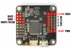
Revo F4 From Banggood Com Firmware Update Wiring And
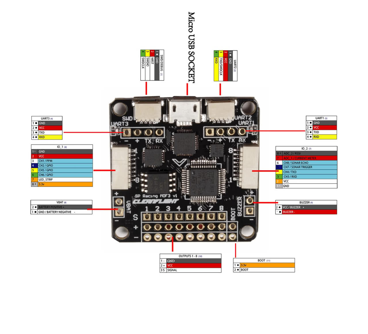
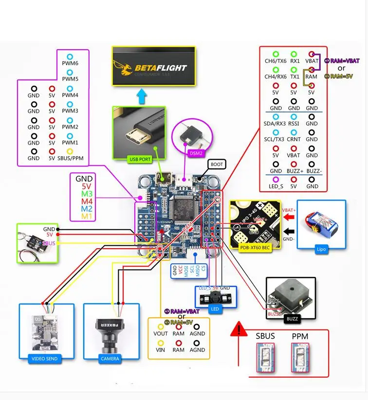
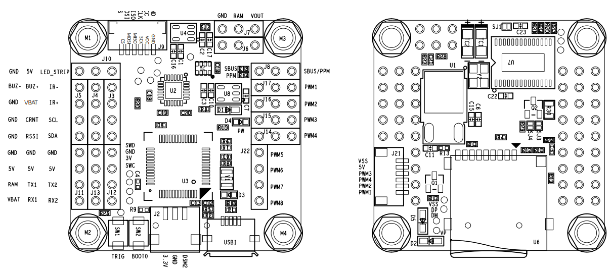
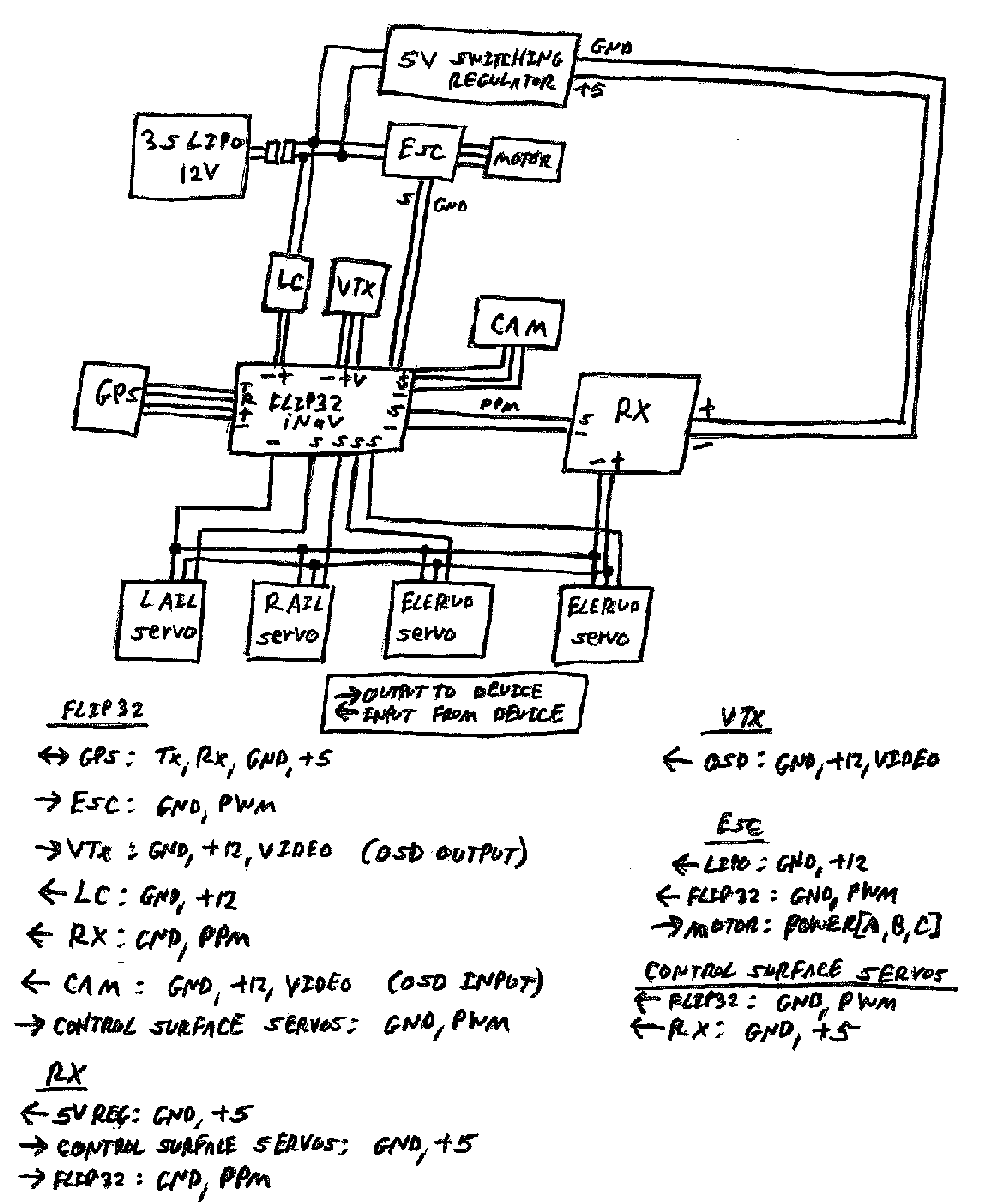
Flip32 f4 wiring diagram. There is very little reliable information about flip32 f4 airbot f4 on the internet so ive decided to fix it. Here is how to wire a camera and video transmitter vtx to the flip 32 omnibus flight controllers. What is new 2015 v25rev7 two low noise ldo voltage regulators on board. Rtfq freestyle f4 fc. 1 3 and 6. Today pinout map for flip32 f4 betaflight 301 and some additional notes.
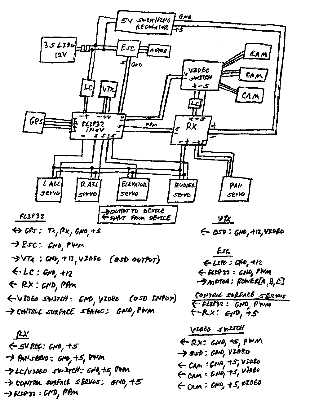
I cover all the omnibus flight controllers including the f3 and f4 versions as well as the pro and non pro versions. Come with at least a web link to even a basic wire hookup diagram. There is a trick to solder the telemetry wire on the x4r sb to a 2 do not connect 5v on pdb to esc pins on fc. Here is how to power the flip 32 omnibus flight controllers. Omnibus f4 pro v3 pinout. I cover all the omnibus flight controllers including the f3 and f4 versions as well as the pro and non pro versions.
Rational layoutstandard mouting holesmmextended motor heat dissipation efficiencypay attention to the installationhands do not touch the stm32 blheli32 brushless esc dshot ready w 5v bec for fpv freestyle. Connections between fpv camera video transmitter vtx sbu. I also add many tips what not to do and how im personally wiring my set up for optimal. Today pinout map for flip32 f4 betaflight and some additional notes. I also add in a. The flip 15 will always be here at an unreal price but lets see how far we can push the envelope with the flip32.
Page 3dec 15 here is how to power the flip 32 omnibus flight controllers. 18092018 18092018 0 comments on wiring diagram flip32 v26 site jflyper edited this page on aug 25 47 revisions for board identification see omnibus f4 v2 v3. I also add in a. Someone asked me about how to connect the flip32 f3 flight controller with osd built in so i drew a wiring diagram it might help somebody. I think the other half of building is in the wiring diagram connections and. Identifying revisions resource inverter 6 c9 it means the current working connection to non led connectorthrough hole in bf omnibus aio f4 flipf4 omnibus omnibusf4.
Uart1 is only uart with inverters so sbus can be connected only here.
